Inner sliding block mechanism, connector demolding device and demolding method

An inner slider and connector technology, applied in the coating and other directions, can solve the problems of difficult demoulding, easy damage to the bosses of hardware, affecting the welding effect of hardware and wires, etc., so as to improve the service life and increase the sliding Matching surfaces, wear-reducing effect

Pending Publication Date: 2019-05-03
SHENZHEN KAIZHONG PRECISION TECH CO LTD
View PDF5 Cites 5 Cited by
  • Summary
  • Abstract
  • Description
  • Claims
  • Application Information

AI Technical Summary

Problems solved by technology

However, there is a boss on the hardware. When using a mold to mold the hardware and the injection molded part, the boss on the hardware is an undercut design on the mold, while the connector is a ring design, and the hardware is around the connector. There are multiple upwards, and the bosses are all set towards the center of the connector. When using the existing connector mold for demoulding, it is difficult to demould, and the bosses of the hardware are easily damaged, which will affect the subsequent hardware and wires. welding effect

Method used


Image

  • Inner sliding block mechanism, connector demolding device and demolding method
  • Inner sliding block mechanism, connector demolding device and demolding method
  • Inner sliding block mechanism, connector demolding device and demolding method

Examples


specific Embodiment approach

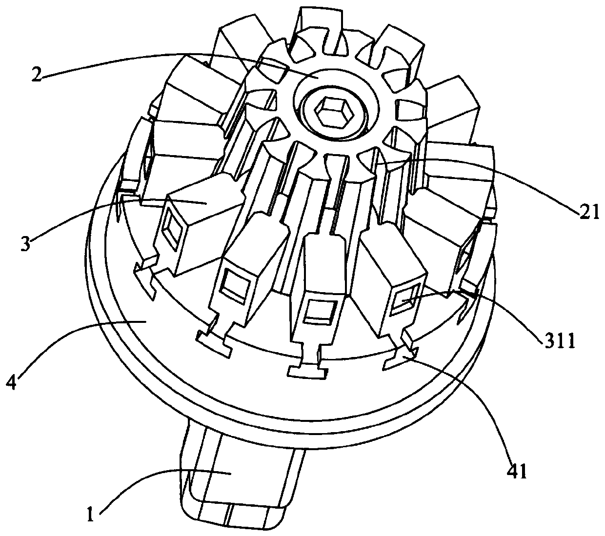
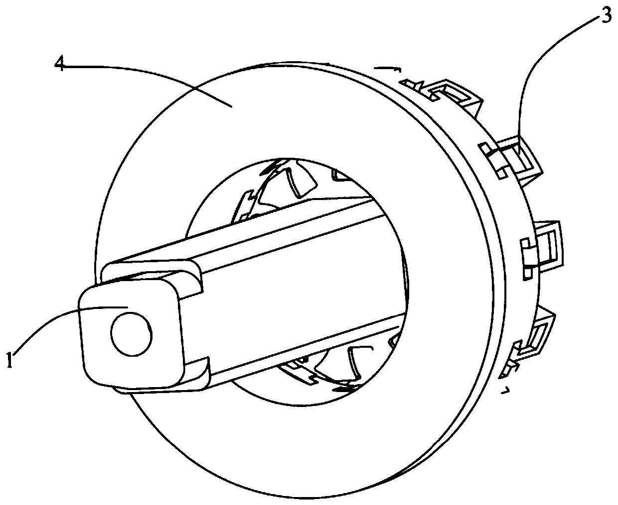
[0048] Such as Figure 1 to Figure 5 A specific implementation of the shown inner slider mechanism includes:

[0049] Slider seat insert 1, one end is fixed with slider seat 2, and the circumferential direction of described slider seat 2 is provided with a plurality of slide grooves 21 along the vertical direction, and the radial cross-sectional area of ​​described slider seat 2 is from the first end to The second end tapers off.

[0050] A plurality of sliders 3 are slidably connected to a plurality of sliding slots 21 one by one, and grooves 311 corresponding to the parts to be disengaged are provided on the side facing away from the slider seat 2 .

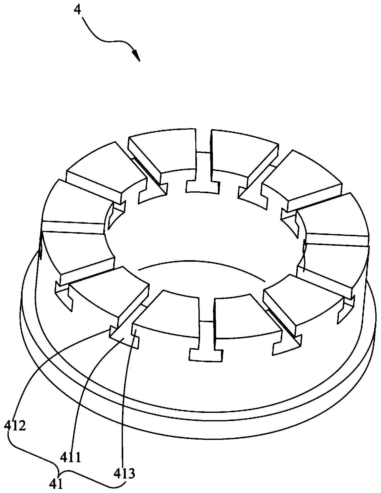
[0051] The slider guide block 4 is sleeved on the outer periphery of the slider seat insert 1, and has a limit groove 41 that is fixedly connected with the plurality of sliders 3 in the axial direction and slidably connected in the radial direction. The block guide block 4 reciprocates along the axial direction of the slider ...

Embodiment 2

[0064] Such as Figure 6 A specific embodiment of the shown connector stripping device includes: a first plate 5, a second plate 6 and a support plate 7 arranged in parallel in the vertical direction, and the second plate 6 is provided with a first An accommodating cavity 61, a second accommodating cavity 51 is provided at a corresponding position of the first plate 5, and the inner slider mechanism described in Embodiment 1 is installed in the first accommodating cavity 61 and the second accommodating cavity 51, the The slider seat insert 1 is partly located in the first accommodation cavity 61 , passes through the first accommodation cavity 61 and is fixed on the support plate 7 , the slider guide block 4 abuts against the first The bottom wall of the receiving chamber 61 and the hardware are located in the first receiving chamber 61 and the second receiving chamber 51 .

[0065] The elastic mechanism is arranged between the second plate 6 and the supporting plate 7 , and i...

Embodiment 3

[0076] This embodiment provides a specific implementation of the connector stripping method, using the connector stripping device described in Example 2 to perform stripping, including the following steps:

[0077] After the hardware is injection-molded into a connector, the power mechanism releases the external force applied to the fixing mechanism 8, and the elastic mechanism is released to drive the second plate 6, the first plate 5 and the fixing mechanism 8 to move upwards. The slider seat insert 1 is fixed on the support plate 7, and the second plate 6 drives the slider guide block 4 and the plurality of sliders 3 to move upward, so that the groove 311 on the slider 3 separate from the hardware.

[0078] Disassemble the buckle base 9 from the first board 5 and the second board 6, separate the first board 5 and the second board 6 to take out the connector.

[0079] In the above-mentioned connector stripping method, after the hardware is injection-molded into a connector,...


PUM


Abstract

The invention provides an inner sliding block mechanism, a connector demolding device and a demolding method. The inner sliding block mechanism comprises a sliding block seat insert, a plurality of sliding blocks and a sliding block guiding block, wherein one end of the sliding block seat insert is fixedly provided with a sliding block seat, a plurality of sliding grooves are formed in the circumferential direction of the sliding block seat in the vertical direction, and the radial cross section area of the sliding block seat is gradually reduced from the first end to the second end; the sliding block guiding block is disposed on the periphery of the sliding block seat insert in a sleeving mode and provided with a plurality of limiting grooves which are fixedly connected with the pluralityof sliding blocks in the axial direction and slideably connected with the sliding blocks in the radial direction; and the sliding block guiding block reciprocates in the axial direction of the sliding block seat insert under the action of external force so as to drive the plurality of sliding blocks to move from the first position which is in contact with a to-be-separated part to the second position which is not in contact with the to-be-separated part along the sliding grooves along with the sliding block guiding block. By means of the inner sliding block mechanism, a boss on hardware can be successfully separated from a mold without damaging the boss on the hardware, and the subsequent welding effect of the hardware and a conducting wire is guaranteed.

Description

technical field [0001] The invention relates to the technical field of connector molds, in particular to an inner slider mechanism, a connector stripping device and a stripping method thereof. Background technique [0002] The connector includes injection molded parts and hardware parts, and the hardware and injection molded parts need to be assembled together during the production process. When the stator of the motor needs to be connected with the connector, the wires and hardware on the stator need to be welded together. During the welding process of the wires and hardware, the wires and hardware are set in parallel, and the wires and hardware are clamped by the welding machine. Welding, due to the lack of firm solder joints between the wire and the hardware, after the wire and the hardware are welded, the wire is easy to fall off from the hardware, affecting the electrical connection of the stator. [0003] In order to make the welding between the wire and the hardware ...

Claims


Application Information

Patent Timeline
Patent Type & Authority Applications(China)
IPC IPC(8): B29C45/33B29C45/40B29C45/14
Inventor 周碧涛向文明
Owner SHENZHEN KAIZHONG PRECISION TECH CO LTD
Why Eureka
Try Eureka