Single lamp indicating type winding mechanism and magnet adsorbing thread residue wire coil winding method

A winding mechanism and indication technology, which is applied in the direction of conveying filamentous materials, thin material handling, transportation and packaging, etc., can solve laborious problems, achieve convenient removal of wire coils, good reliability, and is not easy to scatter wire coils Effect

Active Publication Date: 2019-05-03
泰州镭昇光电科技有限公司
View PDF9 Cites 7 Cited by
  • Summary
  • Abstract
  • Description
  • Claims
  • Application Information

AI Technical Summary

Problems solved by technology

[0003] The invention provides a single-light indicating winding mechanism, which solves the existing laborious problem of removing the wire coil from the coil to form a coil without a fixed core

Method used


Image

  • Single lamp indicating type winding mechanism and magnet adsorbing thread residue wire coil winding method
  • Single lamp indicating type winding mechanism and magnet adsorbing thread residue wire coil winding method
  • Single lamp indicating type winding mechanism and magnet adsorbing thread residue wire coil winding method

Examples


Embodiment 1

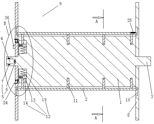
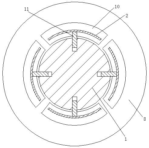
[0022] Embodiment one, see figure 1 , figure 2 , image 3 and Figure 4 , a single-light indicating winding mechanism, including a rotating shaft 1 and a number of winding rods 2 located on the periphery of the rotating shaft and extending axially along the circumferential direction of the rotating shaft. Specifically, there are 4 winding rods. Both ends of the rotating shaft are provided with shaft heads 3 . A counterbore 4 coaxial with the shaft head is provided on the end face of the shaft head. A power introduction structure 5 is arranged inside the counterbore 4 . The power introduction structure includes a conductive block 6 arranged on the bottom wall of the counterbore and a conductive ring 7 arranged on the peripheral wall of the counterbore and extending along the circumferential direction of the counterbore. End plates 8 are provided at both ends of the rotating shaft. The end plate is sleeved on the shaft head. Both end plates are detachably connected toge...

Embodiment 2

[0024] Embodiment two, the difference with embodiment one is:

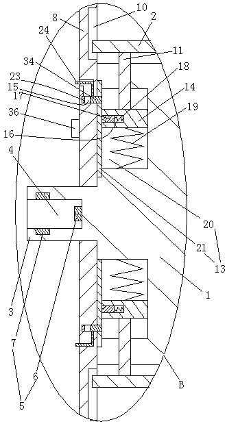
[0025] see Figure 5 . The power introduction structure also includes an insulating plug 26 that is rotatably connected in the counterbore, a first conductive head 27 that abuts against the conductive block on the end surface of the insulating plug, and a conductive head installation hole 28 that is arranged on the peripheral surface of the insulating plug. And the second conductive head 29 pierced in the conductive head installation hole. A third conductive head 30 and a conductive spring 31 that drives the second conductive head to abut against the conductive ring are arranged in the conductive head installation hole. The conductive spring is electrically connected with the second conductive head and the third conductive head. The first conductive head is connected with a first power line 32 , and the third conductive head is connected with a second power line 33 . When in use, the first power line and the s...


PUM


Abstract

Theinvention relates to a single lamp indicating type winding mechanism and a magnet adsorbing thread residue wire coil winding method. The single lamp indicating type winding mechanism comprises a rotary shaft and winding rods, the winding rods are connected with the rotary shaft through sliding rods, the winding rods are provided with winding rod stretching out position locating mechanisms, therotary shaft is provided with a power lead-in structure, a permanent magnet and an indicator light, the winding rod stretching out position locating mechanisms comprise sliding chambers, sliding blocks and locating holes, the sliding blocksare provided with locating pinsand locating springs, the locating pins and the locating springs are matched withthe locating holes, the locating holesare internally provided with contact pairs, the contact pairs of the indicator light, the power lead-in structure and all the winding rod stretching out position locating mechanisms are connected in series, thesliding blocks are connected with the sliding rods, and the magnet adsorbing thread residue winding method is a method that the wire coil winding is conducted through a single lamp indicating type winding mechanism. According to the single lamp indicating type winding mechanism and the magnet adsorbing thread residue wire coil winding method, the problem that a wire coil withouta fixed coreformedthrough taking out a wire coil from a wire spoolneeds great effort is solved.

Description

technical field [0001] The invention relates to the technical field of wire winding, in particular to a single-light indicating type wire winding mechanism and a wire reel method for magnet-adsorbed wire ends. Background technique [0002] In the production process of wire and cable, it is necessary to wind the wire and cable to form a wire coil, and in the production process of the yarn, it is also necessary to wind the yarn together to form a yarn coil (hereinafter, the wire coil and the yarn coil are collectively referred to as a coil. ). Some wire coils are coils with a fixed core formed on the winding reel or bobbin. In order to reduce production costs, it is necessary to wind the wire to be wound into a coil with a fixed core. The existing winding does not have The method of winding the core is to set a baffle at only one end of the winding reel or not to set a baffle at both ends, first wind the wire on the winding reel and then take the winding reel out to form a wi...

Claims


Application Information

Patent Timeline
Patent Type & Authority Applications(China)
IPC IPC(8): B65H54/553B65H54/70B65H75/28B65H67/04
CPCB65H54/553B65H54/70B65H67/0411B65H75/285B65H2301/417B65H2701/34
Inventor 徐德本
Owner 泰州镭昇光电科技有限公司
Why Eureka
Try Eureka