Winch and method for adjusting traction angle of winch

An adjustment method and a technology of traction angle, which is applied in hoisting devices, clockwork mechanisms, etc., can solve problems such as low operating efficiency and automatic change of traction angle, and achieve the effect of improving operating efficiency

Active Publication Date: 2019-05-03
SHANTUI CONSTR MASCH CO LTD
View PDF6 Cites 0 Cited by
  • Summary
  • Abstract
  • Description
  • Claims
  • Application Information

AI Technical Summary

Problems solved by technology

The existing way of adjusting the traction angle of the winch is to manually change the position of the central guide wheel, which has low operating efficiency and cannot automatically change the traction angle according to actual use requirements.

Method used


Image

  • Winch and method for adjusting traction angle of winch
  • Winch and method for adjusting traction angle of winch
  • Winch and method for adjusting traction angle of winch

Examples


Embodiment 1

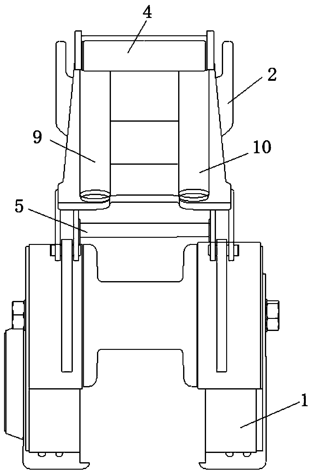
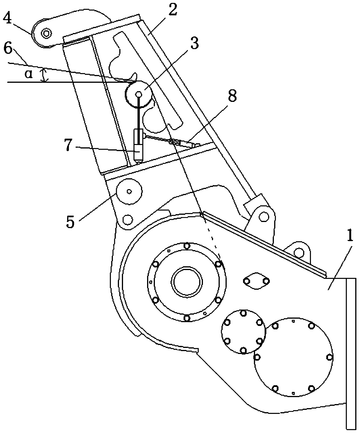
[0036] figure 1 is the front view of the winch provided in this embodiment, figure 2 is a side view of the winch provided in this embodiment, such as figure 1 with figure 2 As shown, this embodiment provides a winch, also known as a winch, which is a light and small lifting and traction device for lifting or pulling heavy objects, and is mainly used in construction, water conservancy projects, gardens, mines, docks and other scenarios to realize The lifting or flat dragging of materials can also be used as supporting equipment on the electronically controlled automatic operation line.

[0037] The winch includes a winch box 1, a reel (not shown), a central guide wheel 3, a first limiting wheel 4 and a second limiting wheel 5, and the winch box 1 plays a supporting role when the winch is used alone The winch can also be used as a lifting component or a traction component in other engineering machinery, such as in engineering machinery such as hoisting machinery, mine hoist...

Embodiment 2

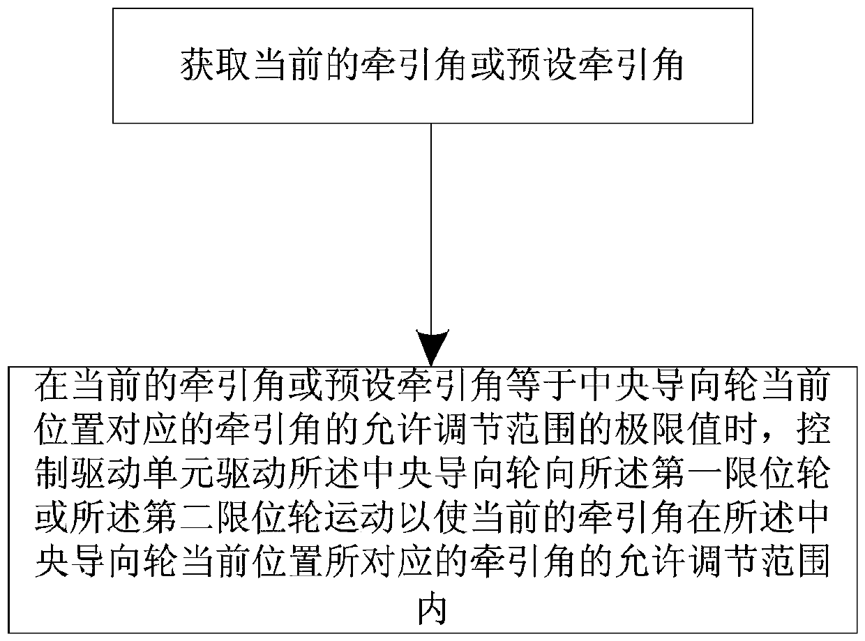
[0093] In this embodiment, the traction angle is adjusted in a continuously changing manner. Specifically, the drive unit includes two drive cylinders, and the movable end and cylinder body of each drive cylinder are respectively hinged to the central guide wheel and the guide frame, and the guide frame and the central guide Wheel sliding fit, such as slide rails and chute, etc., at the same time support the central guide wheel through two driving cylinders, and drive the central guide wheel to move a unit distance each time through the control unit, so that the current traction angle corresponds to the current position of the central guide wheel within the allowable adjustment range of the traction angle.

[0094] Of course, compared with Embodiment 1, the central guide wheel in this embodiment is only supported by two driving cylinders, and the stability is poor.


PUM


Abstract

The invention relates to the field of traction machines, and particularly discloses a winch and a method for adjusting the traction angle of the winch. The winch comprises a winch box, a first limiting wheel, a second limiting wheel and a central guiding wheel, wherein the central guiding wheel can rotate relative to the winch box, and one end of a traction rope is guided by the central guiding wheel and then used for connecting a traction and / or lifting object; and the winch further comprises an angle sensor and a driving unit, wherein the angle sensor is used for measuring the traction angleformed by the traction rope guided by the central guiding wheel and the datum plane, the central guiding wheel is located between the first limiting wheel and the second limiting wheel so as to limitthe allowable adjustment range of the traction angle, and the driving unit can drive the central guiding wheel to move towards the first limiting wheel or the second limiting wheel so as to enable the current traction angle or a preset traction angle to be within the allowable adjustment range of the traction angle corresponding to the current position of the central guiding wheel. The problem that the touch rope touches the first limiting wheel or the second limiting wheel and consequently affects traction force or lifting force is solved through the winch.

Description

technical field [0001] The invention relates to the field of traction machinery, in particular to a winch and a method for adjusting its traction angle. Background technique [0002] The winch is used to drag the goods by retracting and unwinding the wire rope wound on the drum, and can be widely used in heavy lifting and large traction work occasions. As a component of machinery such as lifting, road construction, forestry and mine hoisting, the winch is generally used together with the ripper as an optional device for the rear working device of the bulldozer. [0003] Due to the different heights of the objects to be towed, in order to maximize the traction force and improve the work efficiency, the corresponding traction angles are also different. The way of adjusting the traction angle of the existing winch is to manually change the position of the central guide wheel, the work efficiency is low, and it is impossible to automatically change the traction angle according ...

Claims


Application Information

Patent Timeline
IPC IPC(8): B66D1/28B66D1/36
Inventor 杨丽霞关祥龙张林振胡英华黄亚军刘燕路青青赵娜
Owner SHANTUI CONSTR MASCH CO LTD
Why Eureka
Try Eureka