
Canal bottom lining machine with herringbone two-way concrete scraper mechanism

A herringbone and concrete technology, applied in artificial waterways, water conservancy projects, buildings, etc., can solve problems such as large space occupation, unsuitable use, and complex structure

Pending Publication Date: 2019-05-03
中电建(洛阳)装配式建筑科技有限公司 +1
View PDF0 Cites 0 Cited by
  • Summary
  • Abstract
  • Description
  • Claims
  • Application Information

AI Technical Summary

Problems solved by technology

When paving the canal bottom project, electric spiral paving devices are widely used at present. Electric spiral paving devices need to be equipped with special motors, reducers and other driving devices. Not only the structure is complex, electric drive is required, it takes up a lot of space, and the cost is high.
Moreover, there are problems such as difficulty in replacing worn parts and difficulty in maintenance in the later stage
[0004] Since the material distribution method is left and right reciprocating, when the paving scraper is used to pave the concrete, the direction of the paving slab must change with the change of the paving direction, so as to meet the purpose of always paving the concrete forward. Equipped with a power device for rotating the paving scraper, it not only has problems such as complex structure, high failure rate in use, and high construction cost
Moreover, because the electric scraper takes up a lot of space in the vertical direction, it is not suitable for use in large-scale canal bottom concrete lining projects.

Method used


Image

  • Canal bottom lining machine with herringbone two-way concrete scraper mechanism
  • Canal bottom lining machine with herringbone two-way concrete scraper mechanism
  • Canal bottom lining machine with herringbone two-way concrete scraper mechanism

Examples


no. 1 example

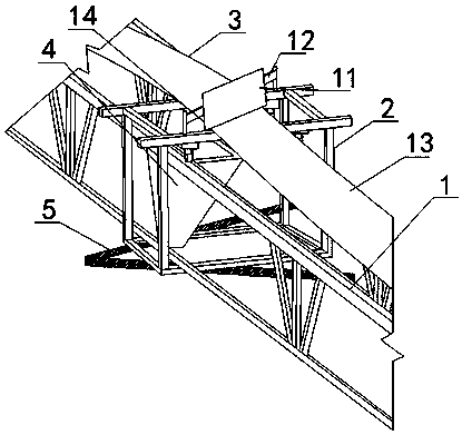
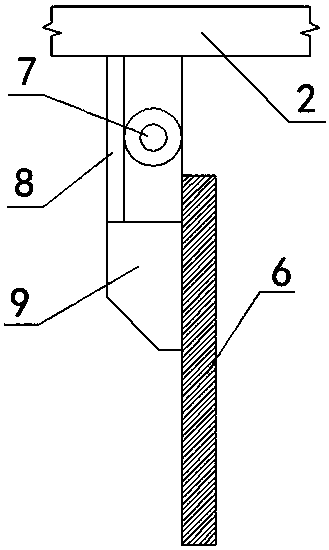
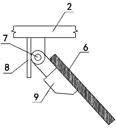
[0023] The first embodiment, such as figure 1 , figure 2 , image 3 and Figure 4 Shown: a trench bottom lining machine with a herringbone bidirectional concrete scraper mechanism, which includes: a truss 1, a paving trolley 2 arranged on the truss 1 and a conveying device 3 arranged on the top of the truss 1, It also includes a scraper mechanism 5 and a lower hopper 4 arranged on the paving trolley 2, and the feeding port of the lower hopper 4 is arranged at the output end 14 of the conveying device 3; the scraper mechanism 5 includes a scraper Plate 6, hinge 7, upper stopper 8 and lower stopper 9, the scraper 6 is arranged at the bottom of the paving trolley 2 through the hinge 7, and the upper stopper 8 is arranged at the hinge 7. The upper part of the outer side, the lower block 9 is arranged on the lower part of the outer side of the hinge 7, the upper block 8 and the lower block 9 can be rotated and abutted outward according to the hinge 7, and the scraper There are...


PUM


Abstract

The invention relates to a canal bottom lining machine with a herringbone two-way concrete scraper mechanism. The canal bottom lining machine with the herringbone two-way concrete scraper mechanism comprises a truss, a paving trolley, a conveying device, a discharging hopper, and two groups of the scraper mechanisms, wherein the paving trolley is arranged on the truss, the conveying device is arranged at the top of the truss, and the discharging hopper is arranged on the lower part of the output end of the conveying device; each scraper mechanism comprises a scraping plate, a hinge, an upper stop block and a lower stop block, the scraping plates are arranged at the bottom of the paving trolley through the hinges, the upper stop blocks are arranged on the upper parts outside the hinges, thelower stop blocks are arranged on the lower parts outside the hinges, and the upper stop blocks and the lower stop blocks can rotate and abut against each other according to the hinges; and the two groups of the scraper mechanisms are arranged in a herringbone mirror image mode, and the discharging hopper is arranged between the two groups of the scraper mechanisms. The canal bottom lining machine with the herringbone two-way concrete scraper mechanism has a simple overall structure, the operation is convenient, the construction efficiency is improved, and probability of mechanical failure and construction cost are reduced; and additional electric equipment and manual participation are not needed during paving, energy is saved, and labor intensity of construction personnel is reduced.

Description

technical field [0001] The invention relates to the field of concrete paving, in particular to a trench bottom lining machine with a herringbone bidirectional concrete scraper mechanism. Background technique [0002] During the construction of the canal bottom concrete, after the concrete is dropped from the conveying device to the working surface by the canal bottom concrete lining machine, a paving device is required to spread the accumulated concrete. [0003] Existing concrete paving devices are divided into two forms: electric screw paving devices and electric scraper paving devices. When paving canal bottom works, electric spiral paving devices are widely used at present. Electric spiral paving devices need to be equipped with special motors, reducers and other driving devices, which not only have complex structure, require electric drive, take up a lot of space, and have high costs. Moreover, there are problems such as difficulty in replacing wear parts and difficult...

Claims


Application Information

Patent Timeline
IPC IPC(8): E02B5/02
Inventor 徐光建彭文波肖明方高海成李湘宁
Owner 中电建(洛阳)装配式建筑科技有限公司
Learn More