An automatic identification control method for a fixed marker

A fixed identification and automatic identification technology, applied in the field of the Internet of Things, can solve the problems of terminal use limitations, inconvenient portability, high energy consumption, etc., and achieve the effect of increasing application occasions or coverage areas, easy and accurate acquisition, and comprehensive and accurate information

Inactive Publication Date: 2019-05-03
HUBEI ZHIBEN INFORMATION TECH
View PDF2 Cites 6 Cited by
  • Summary
  • Abstract
  • Description
  • Claims
  • Application Information

AI Technical Summary

Problems solved by technology

However, there are obvious defects or deficiencies in the above-mentioned terminals: 1) The collection of information depends on two-dimensional code identification or RFID / NFC tags, that is, two-dimensional code identification or RFID / NFC tags need to be set on the object to be processed in advance , so that the scope of use and application of the terminal are greatly limited; 2) It is impossible to collect or identify the status and environment of the terminal operator, especially for the fields that need to collect the above information, such as the field of administrative law enforcement, etc., making the terminal The use is limited; 3) The printing device of the terminal is usually very large, inconvenient to carry and consumes a lot of energy. Hand-held terminals with high requirements for portability and energy consumption cannot be satisfied by the current printing device, especially in some fields. Printing sticker-type notices or information lists, which are not up to the mark in terms of portability and power consumption

Method used


Image

  • An automatic identification control method for a fixed marker
  • An automatic identification control method for a fixed marker
  • An automatic identification control method for a fixed marker

Examples


Embodiment Construction

[0021] The present invention will be described in further detail below in conjunction with the accompanying drawings and embodiments. It should be understood that the specific embodiments described here are only used to explain the present invention, not to limit the present invention.

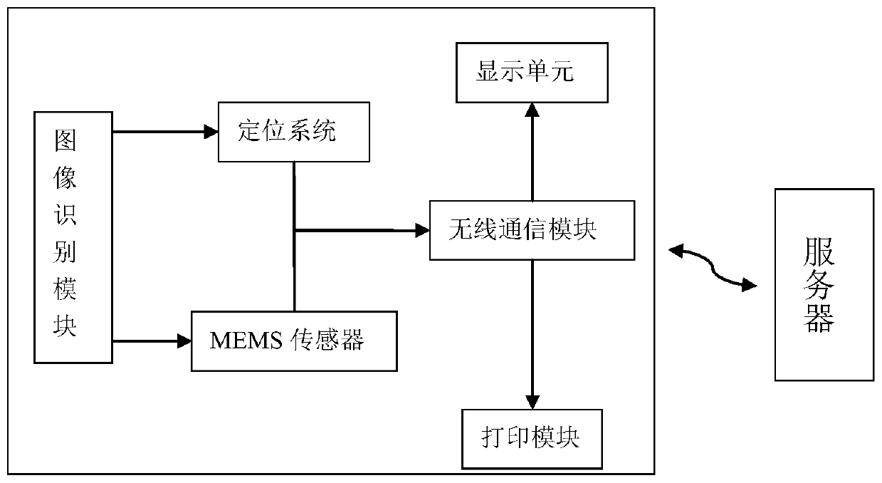
[0022] According to an embodiment of the present invention, the automatic identification control method for fixed markers can not only realize the collection of information without relying on two-dimensional code identification or RFID / NFC tags, but also the information collected in real time can include the status information of the terminal operator and Environmental information, especially portable and real-time detection and processing can be realized.

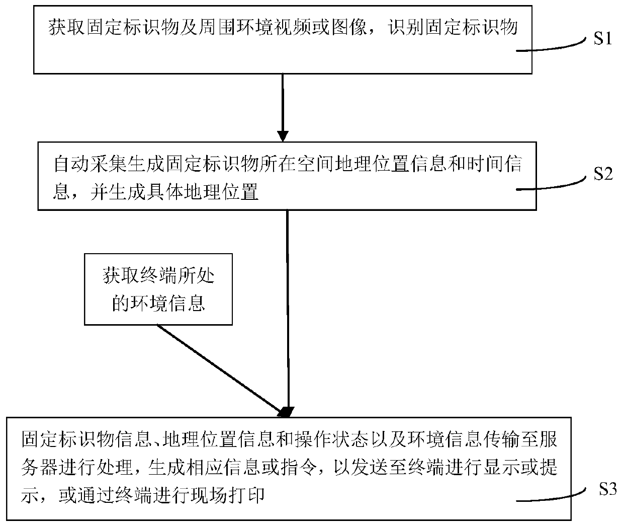
[0023] The automatic identification and control method for fixed markers in this embodiment can realize automatic identification of fixed markers and perform corresponding processing or control accordingly. The method includes:

[0024] S...


PUM


Abstract

The invention discloses an automatic identification control method for a marker, and the method comprises the steps: obtaining a fixed marker and a surrounding environment video and/or image of the fixed marker, obtaining the feature code information of the fixed marker, and automatically identifying the fixed marker; when the image acquisition module acquires videos or images of the fixed markersand surrounding environments of the fixed markers, spatial geographic position information and time information of the fixed markers are automatically acquired and generated, and specific position information represented by road names and/or buildings is generated; sensing the spatial attitude of the terminal by using an attitude acquisition module to sense the operation state of a terminal operator in real time; and transmitting the fixed marker information, the geographic position information, the operation state and the environment information to a server, generating a bill or image whichcorresponds to the fixed marker and carries terminal posture information, and displaying and/or printing and outputting the bill or image through a terminal. The state information of a terminal operator and the information of the environment where the terminal operator is located can be collected in real time, and portable and real-time detection and processing of corresponding markers are achieved.

Description

technical field [0001] The invention belongs to the technical field of the Internet of Things, and in particular relates to a control method for automatic identification of fixed markers. Background technique [0002] The core of the Internet of Things application includes information collection, interconnection transmission, data processing and corresponding control. Among them, the collection of information and the control after processing need to be carried out by means of the terminal, that is, the information is collected through the terminal to identify the item, and the information is connected to the server through the communication transmission module on the terminal for transmission. Information or instructions are transmitted to the terminal through the network, and the control terminal performs corresponding display, processing and control. [0003] At present, there are various terminal devices in Internet of Things applications. For example, the patent documen...

Claims


Application Information

Patent Timeline
Patent Type & Authority Applications(China)
IPC IPC(8): G06K17/00G06K9/00H04L29/08
Inventor 曾秀芳
Owner HUBEI ZHIBEN INFORMATION TECH
Why Eureka
Try Eureka