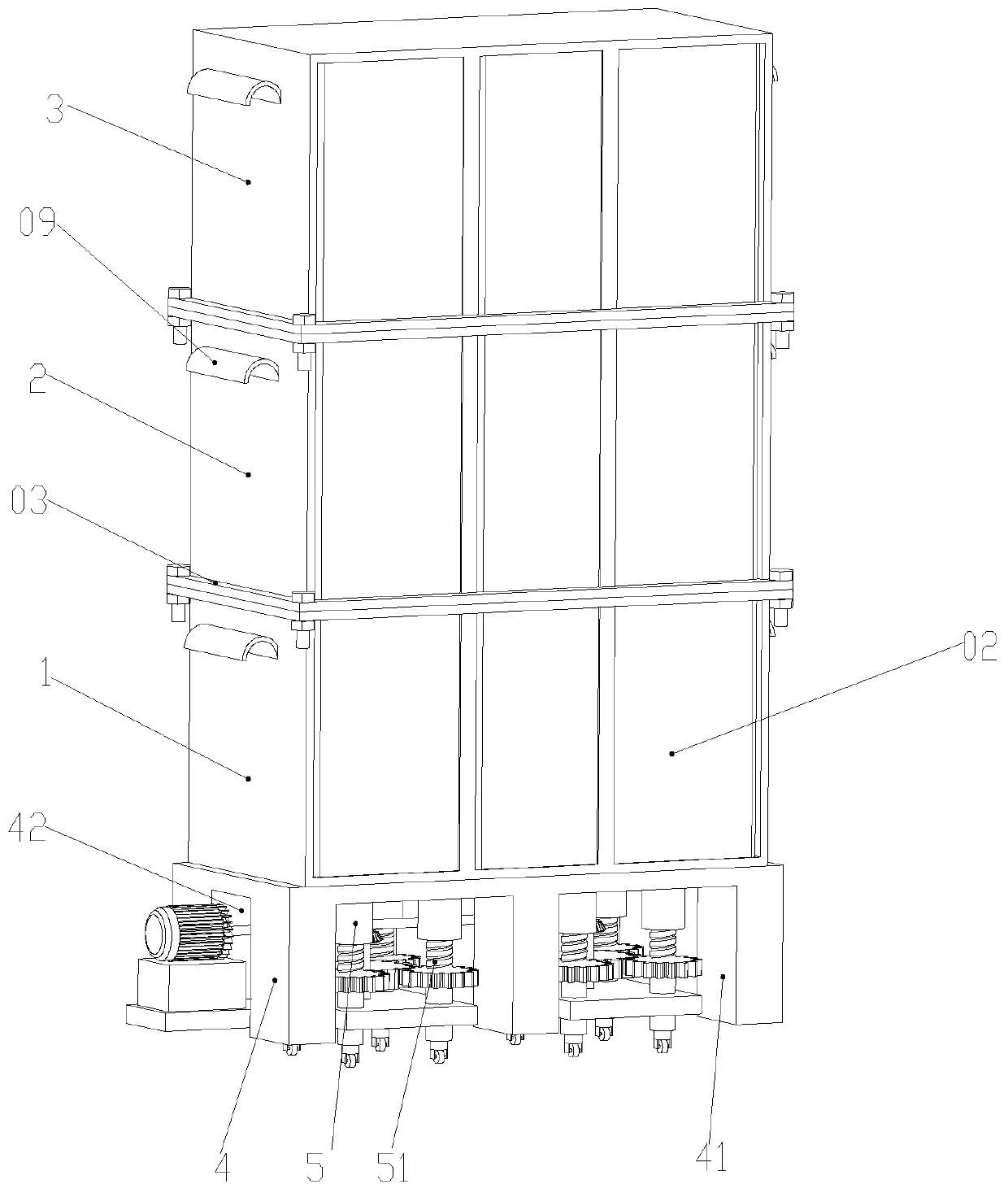
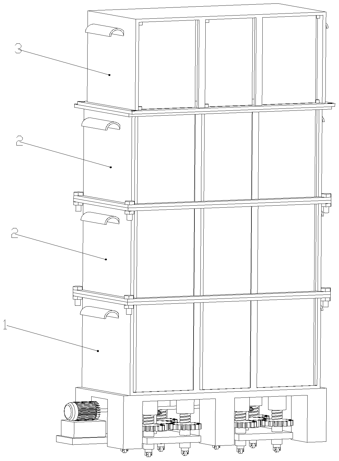
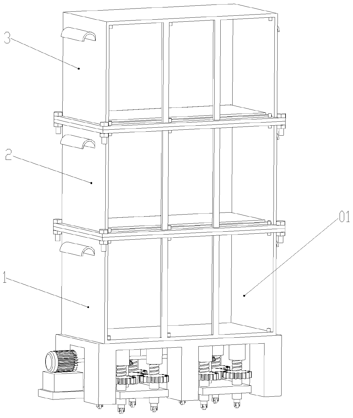
Mobile power distribution room and using method thereof

A technology of power distribution room and distribution box, applied in substation/power distribution device casing, electrical components, substation/switch arrangement details, etc., which can solve the problems of complex assembly process, fixed structure, long construction period, etc.

Inactive Publication Date: 2019-05-03
六安科耐德电气有限公司
View PDF3 Cites 0 Cited by
  • Summary
  • Abstract
  • Description
  • Claims
  • Application Information

AI Technical Summary

Problems solved by technology

[0002] In the process of building construction, it is often necessary to build some temporary power distribution rooms to meet the electricity demand of the construction site. When the assembly process of traditional power distribution rooms is complicated, the construction period is long, and the formed product structure is fixed, it cannot be used in turnover, and the construction site changes. , it is necessary to rebuild a new power distribution room, resulting in a waste of resources
[0003] At the same time, when the height of the power distribution equipment is too high, there are the following problems: it is inconvenient to install the power distribution equipment into the power distribution room from the opening of the sealed door of the power distribution room, or because the height of the power distribution room cannot be increased, the height of the power distribution equipment is higher than that of the distribution room. The internal height of the power room, so that the power distribution room cannot reproduce the power distribution equipment

Method used


Image

  • Mobile power distribution room and using method thereof
  • Mobile power distribution room and using method thereof
  • Mobile power distribution room and using method thereof

Examples


Embodiment Construction

[0035] The following will clearly and completely describe the technical solutions in the embodiments of the present invention with reference to the accompanying drawings in the embodiments of the present invention. Obviously, the described embodiments are only some, not all, embodiments of the present invention. Based on the embodiments of the present invention, all other embodiments obtained by persons of ordinary skill in the art without creative efforts fall within the protection scope of the present invention.

[0036] In describing the present invention, it is to be understood that the terms "opening", "upper", "lower", "thickness", "top", "middle", "length", "inner", "surrounding" etc. Indicating orientation or positional relationship is only for the convenience of describing the present invention and simplifying the description, and does not indicate or imply that the components or elements referred to must have a specific orientation, be constructed and operated in a sp...


PUM


Abstract

The invention discloses a mobile power distribution room, and the power distribution room comprises a bottom housing, a middle housing and a top housing. A middle housing is overlapped between the bottom housing and the top housing. A supporting pedestal is fixedly installed at the lower end of the bottom housing, and a first rectangular groove and a second rectangular groove are formed in the supporting pedestal. A first supporting column is arranged at the top of the first rectangular groove, a second supporting column is arranged in the first supporting column, and a supporting disc is arranged at the lower end of the second supporting column, wherein universal wheels are arranged at the lower end of the supporting disc. When in use, the number of middle housings of the power distribution room can be increased or decreased according to actual conditions; when large power distribution equipment needs to be placed in a power distribution box, the large power distribution equipment isfirstly placed at the upper end of the bottom housing through the upper end of the bottom housing, then the middle housing is arranged at the outer side of the large power distribution equipment one by one in a sleeving mode, finally the top housing is placed. Due to the fact that the universal wheels are arranged at the bottom end, short-distance movement of the power distribution room can be conveniently conducted.

Description

technical field [0001] The invention relates to a power distribution room, in particular to a mobile power distribution room and its usage method. Background technique [0002] In the process of building construction, it is often necessary to build some temporary power distribution rooms to meet the electricity demand of the construction site. When the assembly process of traditional power distribution rooms is complicated, the construction period is long, and the formed product structure is fixed, it cannot be used in turnover, and the construction site changes. , it is necessary to rebuild a new power distribution room, resulting in a waste of resources. [0003] At the same time, when the height of the power distribution equipment is too high, there are the following problems: it is inconvenient to install the power distribution equipment into the power distribution room from the opening of the sealed door of the power distribution room, or because the height of the power...

Claims


Application Information

Patent Timeline
Patent Type & Authority Applications(China)
IPC IPC(8): H02B1/26H02B1/50H02B1/28
Inventor 黄丙宽
Owner 六安科耐德电气有限公司
Why Eureka
Try Eureka