Hydraulic lifting support for coal conveying belt
A technology of hydraulic lifting and belt, applied in the direction of lifting frame, lifting device, etc., can solve the problems such as the danger of occupying the site and the difficulty of lifting heavy belts by a motor forklift, and achieve the effect of reducing risks, saving labor costs, and being easy to use.
- Summary
- Abstract
- Description
- Claims
- Application Information
AI Technical Summary
Problems solved by technology
Method used
Image
Examples
Embodiment 1
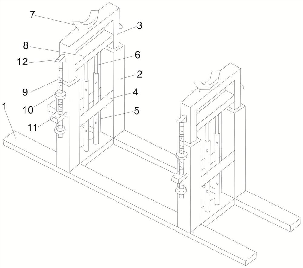
[0037] see figure 1 As shown in the hydraulic lifting support for a coal conveyor belt, place the support well. At this time, the two branch grooves are parallel, and the two branch grooves 7 hold up the belt. When the belt needs to be replaced, start the hydraulic cylinder 5, and the hydraulic cylinder 5 jack up the hydraulic rod 6, the hydraulic rod 6 jacks up the supporting rod 3, and the supporting rod 3 will move up with the position limited by the lifting rod 2. There are two hydraulic cylinders 5, which are arranged on the lifting rod 2 In the middle, the hydraulic rod 6 is installed on the hydraulic cylinder 5, and the two hydraulic cylinders 5 on both sides are lifted at the same time, which can avoid the belt from being deflected due to uneven force. When the supporting rod 3 is lifted, use The nut 10 locks the safety screw limit block 11, the safety screw limit block 11 and the nut 10 fix the safety screw 9, and the safety screw 9 supports the top block 12, so that ...
Embodiment 2
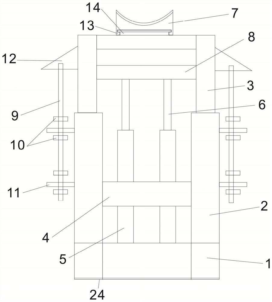
[0039] see figure 2 In the shown hydraulic lifting support for a coal conveyor belt, in embodiment 2, on the basis of embodiment 1, a rubber pad 24 is provided at the bottom of the support 1, and the rubber pad 24 is arranged around the bottom edge of the support 1, which can So that the bracket will not wear the ground. A chute 13 is set below the branch groove 7, and a slide table 14 is set on the top of the supporting rod 3. The slide table 14 is T-shaped, and the chute 13 and the slide table 14 can be fitted together. The branch grooves 7 have different sizes and specifications and can be replaced. On the left side and the right side of the lifting rod 2, one more safety screw limit block 11 is respectively arranged, and the nuts 10 are respectively arranged on the safety screw 9, and the nuts 10 are arranged in pairs. On the safety screw 9, the nuts 10 are respectively located above and below the newly set safety screw stop blocks 11, and the two safety screw stop bloc...
Embodiment 3
[0041] see image 3 In the shown coal belt hydraulic lifting support, on the basis of embodiment 1, several roller shafts 21 and rollers 22 are arranged under the support 1, and the roller shafts 21 are connected inside the support 1 , the roller 22 is installed on the roller shaft 21, so that the support can be moved as a whole, and several roller boxes 23 are arranged under the support 1, and the roller shaft 21 and the roller 22 are arranged in the roller box 23, The roller shaft 21 is connected in the roller box 23, the roller 22 is mounted on the wheel shaft 21, a connecting plate 26 is arranged above the roller box 23, and a roller elevating rod is arranged above the connecting plate 26 25. The roller box 23 can be raised and lowered by the roller elevating lever 25, so that the roller 22 can move up and down. When not in use, the roller 22 can be put away to prevent the support from sliding.
[0042] When the support needs to move, start the roller lifting lever 25, th...
PUM
 Abstract
Description
Claims
Application Information
 - R&D
- Intellectual Property
- Life Sciences
- Materials
- Tech Scout
- Unparalleled Data Quality
- Higher Quality Content
- 60% Fewer Hallucinations
Browse by: Latest US Patents, China's latest patents, Technical Efficacy Thesaurus, Application Domain, Technology Topic, Popular Technical Reports.
© 2025 PatSnap. All rights reserved.Legal|Privacy policy|Modern Slavery Act Transparency Statement|Sitemap|About US| Contact US: help@patsnap.com


