An ultra-deep shaft hoist and hoisting method

A technology for hoists and vertical shafts, which is applied to lifting equipment, transportation and packaging in mines. It can solve the problems of lowering lifting efficiency, increasing lifting risks, and increasing the weight of steel wire ropes, so as to improve service life, reduce lifting risks, and increase The effect of greatly improving efficiency

Active Publication Date: 2020-02-07
CHINA UNIV OF MINING & TECH
View PDF6 Cites 0 Cited by
  • Summary
  • Abstract
  • Description
  • Claims
  • Application Information

AI Technical Summary

Problems solved by technology

For the mining of shallow mines, multi-rope friction hoisting is generally used, but for ultra-deep mine hoisting, the self-weight of steel wire ropes increases greatly, which will increase the risk of hoisting and reduce the hoisting efficiency, so winding hoisting can only be used. This paper proposes One is a hoist for ultra-deep mines

Method used


Image

  • An ultra-deep shaft hoist and hoisting method
  • An ultra-deep shaft hoist and hoisting method
  • An ultra-deep shaft hoist and hoisting method

Examples


Embodiment 1

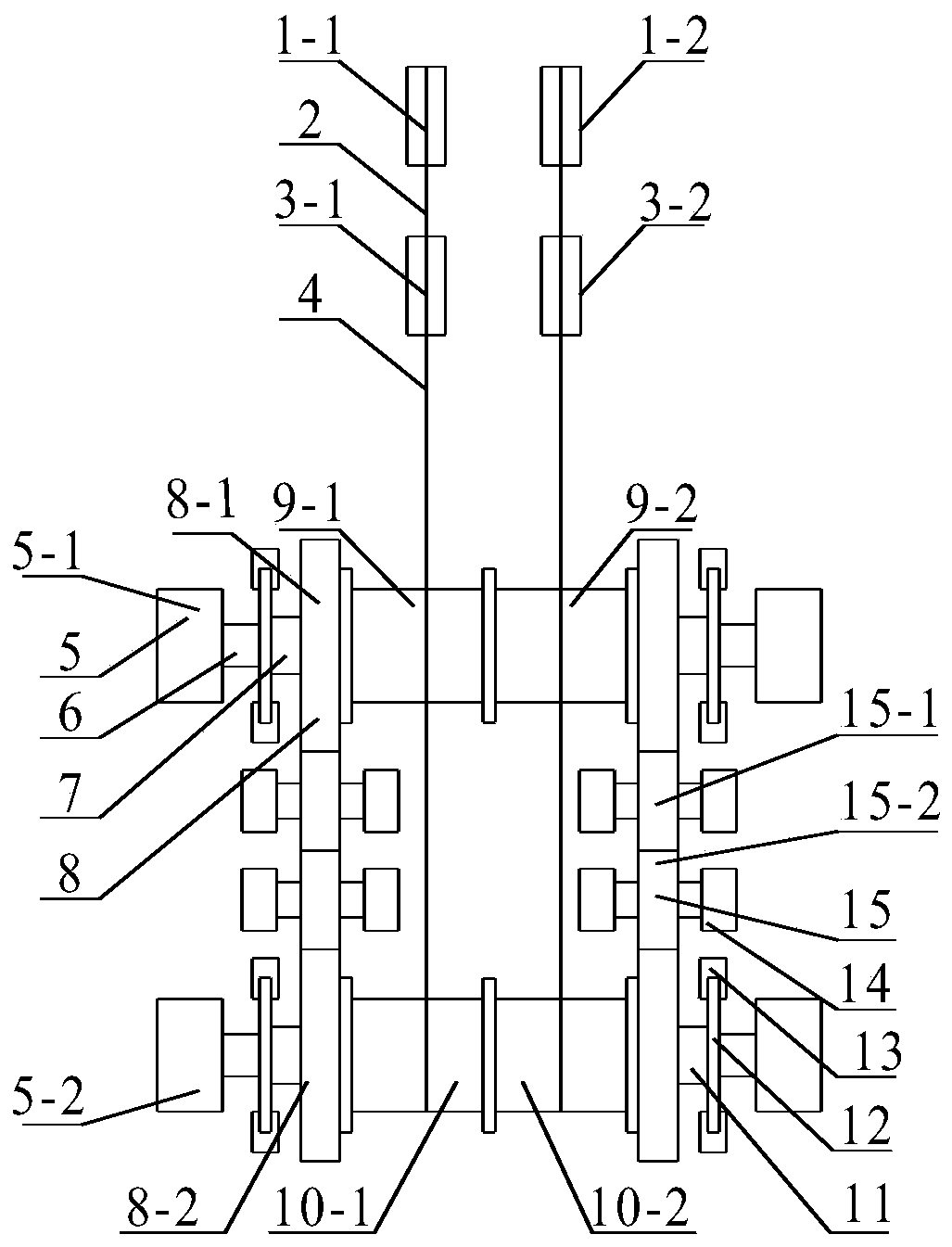
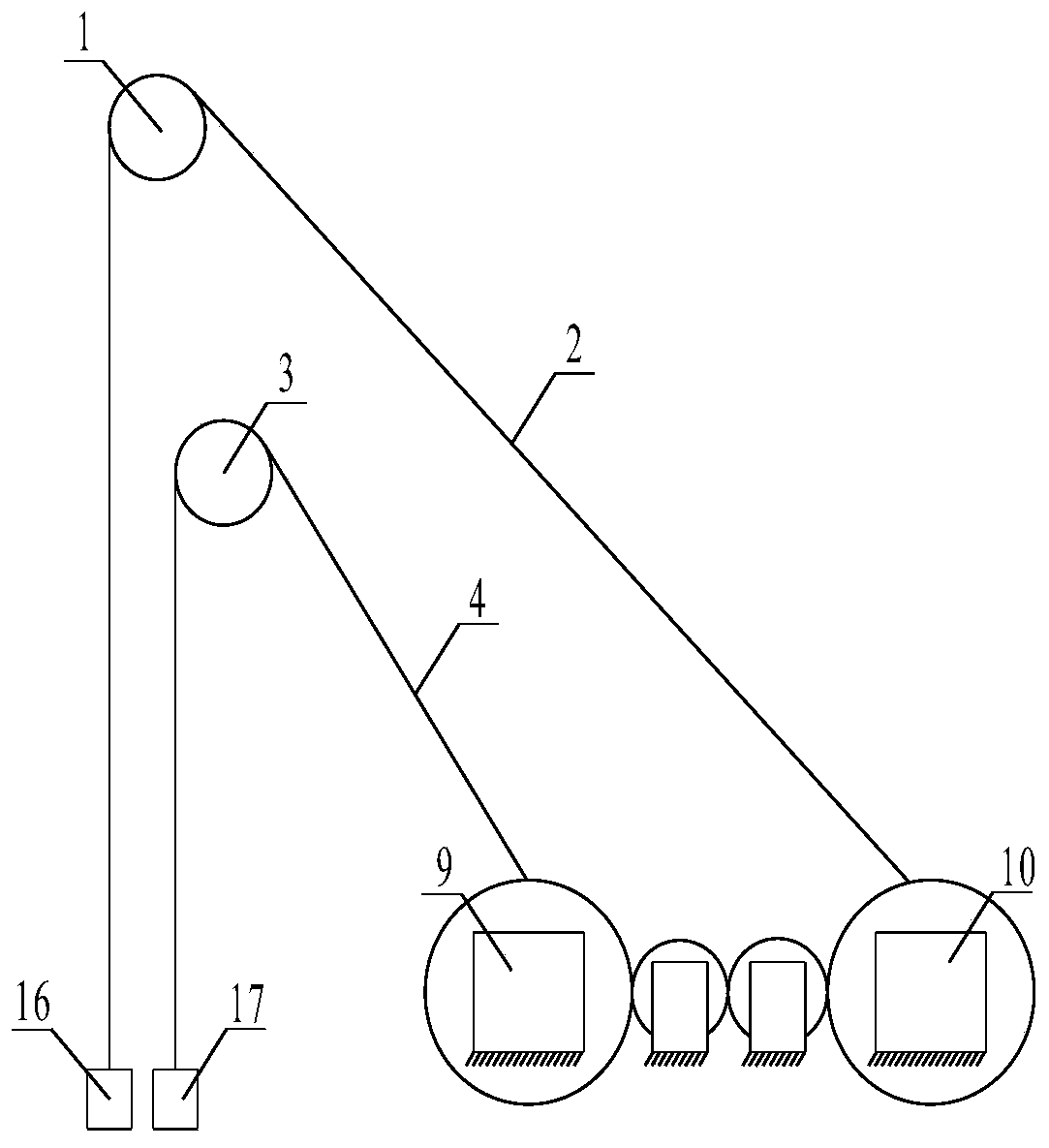
[0025] Example 1, such as figure 1 As shown, the ultra-deep vertical shaft hoist of the present invention includes a sky wheel set above the wellhead and a driving device. The driving device controls the wire rope that bypasses the sky wheel and is connected to the lifting container. The sky wheel set includes the upper sky wheel set 1 And the lower wheel set 3; the driving device includes a symmetrically arranged driving motor 5, a front shaft 7, a rear shaft 11, a front roller 9 and a rear roller 10. The front and rear rollers are respectively installed on the front and rear shafts. The left and right ends of the two shafts are respectively provided with a brake disc 12 and a driving motor 5 in sequence; the front shaft 7 and the rear shaft 11 of the driving motor 5 are connected to the output shaft of the driving motor 5 through a coupling 6 respectively. For the left and right driving motors 5 of the front and rear shafts, the steering of the front motor 5-1 connected on bot...

Embodiment 2

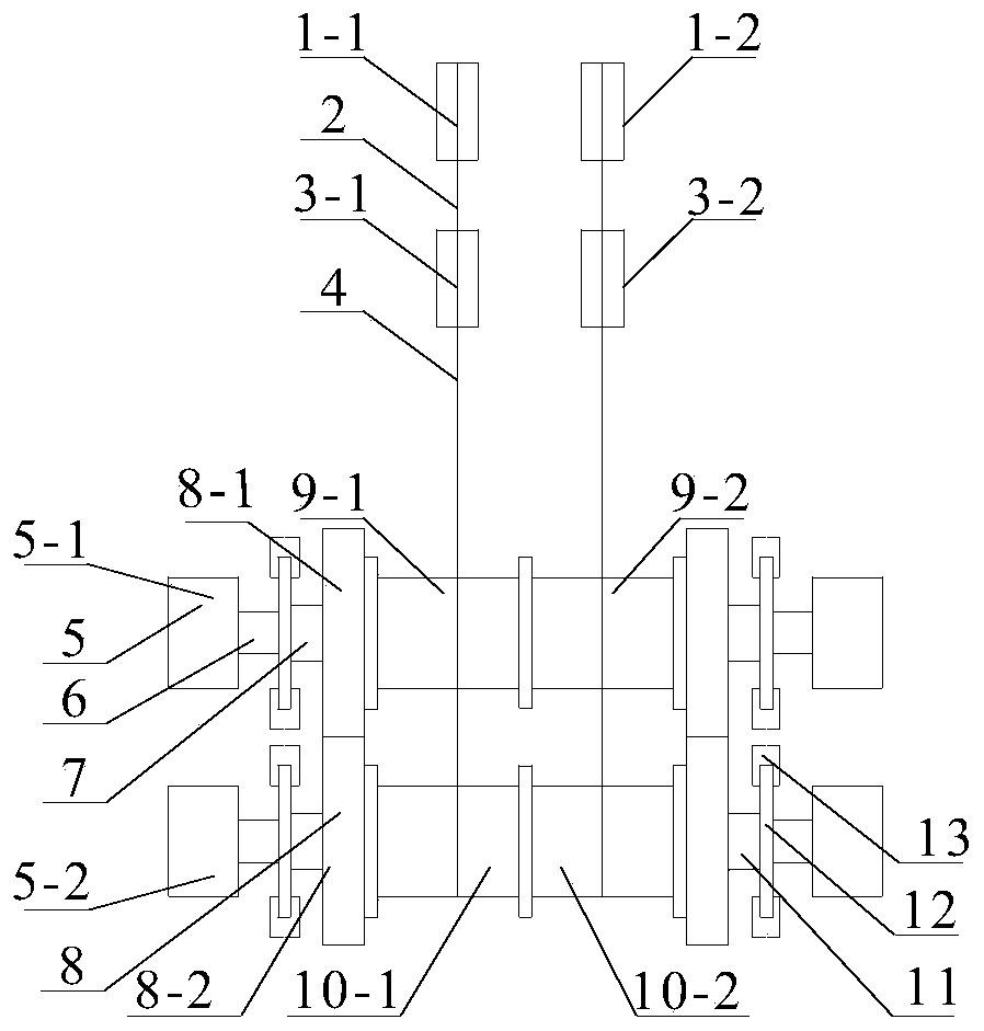
[0028] Example 2, such as image 3 , 4 As shown, it is basically the same as Embodiment 1, and the similarities are omitted. Difference: The number of idlers is 0. The front gear 8-1 and the rear gear 8-2 on the left and right sides of the hoist mesh with each other. When the front wire rope 2 is lifted, the driving motor 5-2 on the rear side rotates clockwise; the rotation direction of the driving motor 5-1 on the front side is opposite to the rotation direction of the rear motor 5-2, which is counterclockwise. When the rear wire rope 4 is lifted, the driving motor 5-1 on the front side rotates clockwise; the rotation direction of the rear motor 5-2 is opposite to the rotation direction of the front motor 5-1, which is counterclockwise.

Embodiment 3

[0029] Example 3, such as Figure 5 , 6 As shown, it is basically the same as in Example 1, and the similarities are omitted. Difference: The number of idlers is 1. The front gear 8-1 and the rear gear 8-2 on the left and right sides of the hoist mesh with an idler gear. The rotation directions of the front and rear driving motors 5-1 and 5-2 are the same, that is: when the front wire rope 2 is lifted, the rear driving motor 5-2 rotates clockwise; the front driving motor 5-1 rotates in the same direction as The direction of rotation of the rear motor 5-2 is the same, clockwise. When the rear wire rope 4 is lifted, the front drive motor 5-1 rotates clockwise; the rotation direction of the rear motor 5-2 is the same as the rotation direction of the front motor 5-1, which is clockwise. The direction of the front and rear steel wire ropes on the drum is exactly opposite, one is the upper rope and the other is the lower rope.

[0030] The lifting method of the ultra-deep vertical s...


PUM


Abstract

The invention discloses an extra deep shaft elevator and an elevating method. The extra deep shaft elevator comprises head sheave sets and a driving device; the head sheave sets comprise the upper head sheave set and the lower head sheave set; the driving device comprises driving motors, a front shaft, a back shaft, a front roller and a back roller which are symmetrically arranged correspondingly, the front roller and the back roller are installed on the front shaft and the back shaft correspondingly, and the left side and the right side of each of the front shaft and the back shaft are each provided with a gear; in the front roller and the back roller, a front elevating steel wire rope wound on the front roller is wound around the lower head sheave set to be connected with a back elevating container, and a back elevating steel wire rope wound on the back roller is wound around the upper head sheave set to be connected with a front elevating container. The manner that the two elevator rollers are connected with the gear sets is adopted, the motor motion synchronism is improved through gear transmission, and the two elevating containers are elevated in the manner that the front and back elevating steel wire rope are wound around the front and back rollers to wind around the head sheave sets; and the extra deep shaft elevator is simple in structure and convenient to operate, the elevating risk is reduced, and the elevating efficiency is improved.

Description

Technical field [0001] The invention relates to a hoist and a hoisting method, in particular to an ultra-deep vertical shaft hoist and a hoisting method suitable for mines. Background technique [0002] Since entering the 21st century, China's economy has developed rapidly. With the increasing shortage of mineral resources and the increasing demand for them from economic development, my country has proposed an important development strategy for the development and utilization of deep resources, which requires us to explore deeper underground. At present, the mining depth of some major mining countries has reached 4000m, while the mining depth in my country is generally less than 1000m. Therefore, deep mining is an inevitable trend for future mineral resources acquisition. The vertical shaft hoist has two types: winding hoist and friction hoist. For shallow mine mining, multi-rope friction lifting is generally used, but for ultra-deep mine lifting, the weight of the wire rope in...

Claims


Application Information

Patent Timeline
Patent Type & Authority Patents(China)
IPC IPC(8): B66B15/06B66B15/08
CPCB66B15/06B66B15/08
Inventor 朱真才曹国华王可彭维红花纯利白迎东周公博彭玉兴李伟
Owner CHINA UNIV OF MINING & TECH
Why Eureka
Try Eureka