Automatic feeding device for material conveying

A technology for feeding equipment and materials, which is applied to conveyor objects, transportation and packaging, loading/unloading, etc., can solve the problems of large size, poor labor-saving effect, and heavy weight of bolt feeders, and achieve convenient short-distance movement and labor-saving effect. Good and practical effect

Inactive Publication Date: 2020-01-14
苏州吉玛自动化科技有限公司
View PDF0 Cites 0 Cited by
  • Summary
  • Abstract
  • Description
  • Claims
  • Application Information

AI Technical Summary

Problems solved by technology

[0003] The bolt feeder in the prior art still has certain deficiencies in use: due to the large volume and heavy weight of the bolt feeder, the movement of the bolt feeder generally depends on manpower to lift, and the bolt feeder is realized in turn. Short-distance movement, the labor-saving effect is very poor, therefore, we propose an automatic feeding equipment for material transportation

Method used


Image

  • Automatic feeding device for material conveying
  • Automatic feeding device for material conveying
  • Automatic feeding device for material conveying

Examples


Embodiment 1

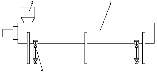
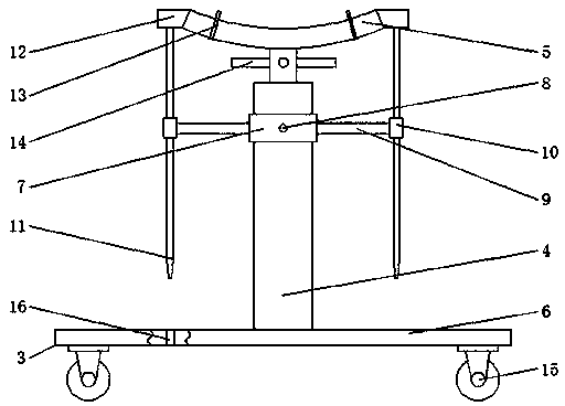
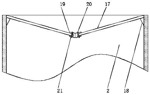
[0022] refer to Figure 1-2 , an automatic feeding device for material conveyance, comprising a screw feeder body 1 and a feed bin 2, the bottom of the screw feeder body 1 is provided with two moving mechanisms 3, and the moving mechanism 3 includes a screw jack 4, the screw jack 4 An arc-shaped plate 5 is fixedly installed on the support ring, and a bottom support plate 6 is fixedly installed on the bottom of the screw jack 4, and a collar 7 is sleeved on the screw jack 4, and four first screws 8 are arranged on the collar 7, The collar 7 is fixedly connected with the screw jack 4 by the first screw 8, the outer surface of both sides of the collar 7 is welded with a connecting crossbar 9, and one end of the connecting crossbar 9 is welded with a limit sleeve 10, and the limit sleeve 10 The limit vertical bar 11 runs through the top, and the two ends of the arc-shaped plate 5 are provided with raised blocks 12, and the raised blocks 12 are welded to the top of the limit vertic...

Embodiment 2

[0025] refer to Figure 1-3 , an automatic feeding device for material conveyance, comprising a screw feeder body 1 and a feed bin 2, the bottom of the screw feeder body 1 is provided with two moving mechanisms 3, and the moving mechanism 3 includes a screw jack 4, the screw jack 4 An arc-shaped plate 5 is fixedly installed on the support ring, and a bottom support plate 6 is fixedly installed on the bottom of the screw jack 4, and a collar 7 is sleeved on the screw jack 4, and four first screws 8 are arranged on the collar 7, The collar 7 is fixedly connected with the screw jack 4 by the first screw 8, the outer surface of both sides of the collar 7 is welded with a connecting crossbar 9, and one end of the connecting crossbar 9 is welded with a limit sleeve 10, and the limit sleeve 10 The limit vertical bar 11 runs through the top, and the two ends of the arc-shaped plate 5 are provided with raised blocks 12, and the raised blocks 12 are welded to the top of the limit vertic...


PUM


Abstract

The invention discloses an automatic feeding device for material conveying. The automatic feeding device for material conveying comprises a screw feeding machine body and a feed bin, wherein two moving mechanisms are arranged on the bottom part of the screw feeding machine body; each moving mechanism comprises a screw rod jack; an arc-shaped plate is fixedly arranged on a support ring of each screw rod jack; a bottom support plate is fixedly arranged on the bottom part of each screw rod jack; a sleeve ring is connected onto each screw rod jack in a sleeving way; four first screws are arrangedon each sleeve ring; each sleeve ring is fixedly connected with the corresponding screw rod jack through the first screws; connecting cross rods are welded to the outer side surfaces of two sides of each sleeving ring; limiting sleeve pipes are welded to one ends of the connecting ross rods; limiting vertical rods penetrate through the limiting sleeve pipes; and bulge blocks are arranged at two ends of each arc-shaped plate. According to the automatic feeding device for material conveying provided by the invention, the lifting of universal wheels is controlled by utilizing the screw rod jacks,so that without influencing the stability of the screw feeding machine, the short-distance movement of the screw feeding machine is realized conveniently, a labor-saving effect is good, and the practicability is high.

Description

technical field [0001] The invention relates to the technical field of feeding equipment, in particular to an automatic feeding equipment for material transportation. Background technique [0002] Generally, the conveying of materials adopts the bolt feeder. The bolt feeder is mainly composed of a screw body composed of a trough, a screw blade and a rotating shaft, bearings at both ends, a middle suspension bearing and a driving device. When the screw body rotates, the material entering the machine tank is received The normal thrust of the rotating blade, the radial component of the thrust and the friction force of the blade on the material will make the material rotate around the axis; while the gravity of the material and the friction force of the machine groove on the material prevent the material from rotating around the axis. The axial component of the normal thrust of the material overcomes the friction force of the trough on the material and the radial component of th...

Claims


Application Information

Patent Timeline
Patent Type & Authority Applications(China)
IPC IPC(8): B65G33/24B65G41/00B65G69/18
CPCB65G33/24B65G41/001B65G69/181
Inventor 饶智超
Owner 苏州吉玛自动化科技有限公司
Why Eureka
Try Eureka