On-line identification method for unbalance of magnetic suspension rotor based on current test mass

A technology of a magnetic suspension rotor and an identification method is applied in the field where the gyro room is inconvenient to disassemble, and can solve the problems of low identification accuracy, inability to realize zero current and zero displacement state at the same time, affecting the stability of the original system, etc.

Active Publication Date: 2014-02-26
BEIHANG UNIV
View PDF5 Cites 24 Cited by
  • Summary
  • Abstract
  • Description
  • Claims
  • Application Information

AI Technical Summary

Problems solved by technology

Active vibration control realizes the rotation of the rotor around the inertial axis and eliminates the disturbing force transmitted to the base, but it also has its own disadvantages: it cannot achieve zero current and zero displacement at the same time, and the beating of the rotor increases the eddy current loss under the condition of high speed and large unbalance.
[0004] At present, online dynamic balancing mainly reduces vibration by adding or subtracting mass blocks to achieve the coincidence of the inertial axis and geometric axis of the rotor; among them, the identification accuracy of unbalance directly affects the effect of online dynamic balancing, and the identification of unbalance in the process of online dynamic balancing There are mainly the following three methods: the first is to use the influence coefficient method for identification, and use the addition and subtraction of mass blocks to test the weight, which requires multiple start-ups. For the magnetic levitation rotor, such as the rotor of th

Method used


Image

  • On-line identification method for unbalance of magnetic suspension rotor based on current test mass
  • On-line identification method for unbalance of magnetic suspension rotor based on current test mass
  • On-line identification method for unbalance of magnetic suspension rotor based on current test mass

Examples


Embodiment Construction

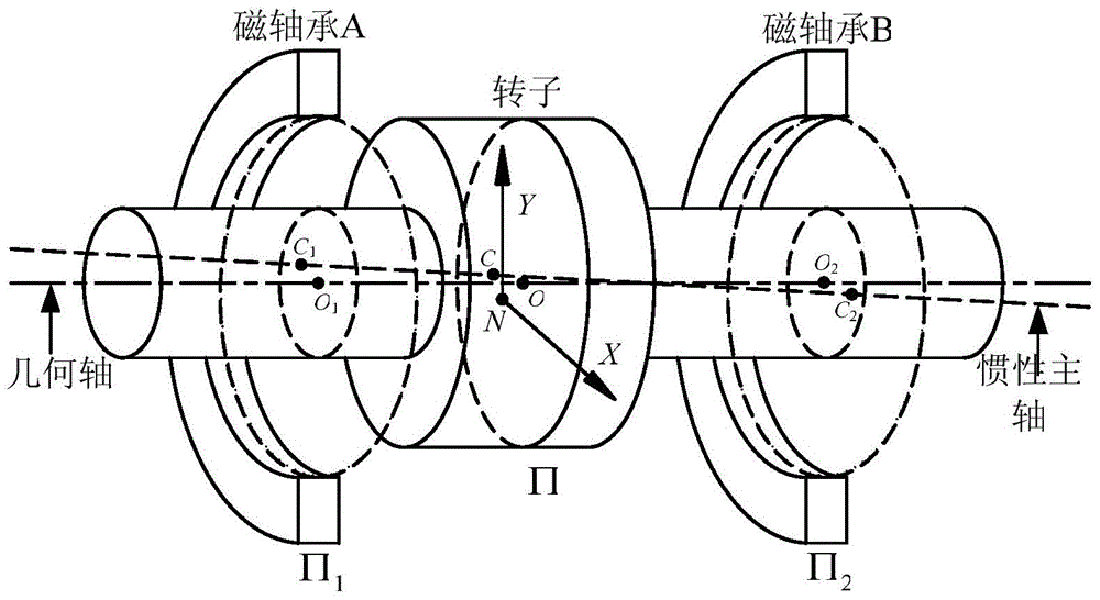
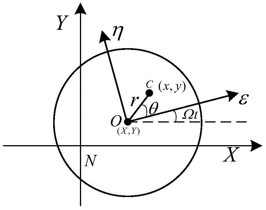
[0059] The maglev rotor system consists of a displacement sensor K s , controller C(s), power amplifier G w (s), the magnetic bearing rotor system P(s), the displacement sensor measures the rotor displacement and feeds it back to the controller, the controller outputs the control quantity to the power amplifier, the power amplifier outputs the current to the magnetic bearing coil, and the magnetic bearing generates force and torque to make The rotor is stably suspended. Due to reasons such as manufacturing and processing, the inertial axis of the rotor does not coincide with the geometrical axis. Among them, the displacement of the geometric center and the center of mass of the rotor is the static unbalance, and the torsional angular displacement of the geometrical axis relative to the inertial axis is the dynamic unbalance of the rotor.

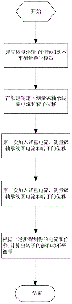
[0060] (1) Establish the static and dynamic unbalance mathematical model of the maglev rotor

[0061] Static and dynamic unbalance of mag...


PUM


Abstract

Provided is an on-line identification method for unbalance of a magnetic suspension rotor based on current test mass. First, a mathematical model of static and dynamic unbalance of the rotor is established, then at rated rotating speed, a current transformer measures a current of a magnetic bearing coil, and a displacement sensor measures the displacement of a radial channel of the magnetic suspension rotor; secondly, the rotating speed is kept unchanged, a test mass current is added for the first time, the current of the magnetic bearing coil is measured, and the displacement of the radial channel of the rotor is measured; at the same rotating speed, the test mass current is added for the second time, the current of the magnetic bearing coil is measured, and the displacement of the rotor on the radial channel is measured; finally, the static and dynamic unbalance of the rotor is identified according to the currents and displacements measured at three times. The on-line identification method is simple and easy to implement by starting a car at one time and is applied to identification of the static and dynamic unbalance of the magnetic suspension rotor in the on-line dynamic balance process.

Description

technical field [0001] The invention relates to an online identification method for the unbalance of a magnetic suspension rotor based on a current test weight, which is used for identification of static and dynamic unbalance during the dynamic balancing process of the magnetic suspension rotor, and is especially suitable for the occasion where the gyro room of the magnetic suspension control moment gyro is inconvenient to disassemble. Background technique [0002] Magnetic levitation control moment gyroscope is the key actuator for attitude control of large spacecraft such as space station. The rotor is supported by magnetic bearings. Compared with traditional mechanical contact bearings, it has the characteristics of no contact friction, long life, low energy consumption, and no need for lubrication. [0003] During the processing, manufacturing and assembly of the rotor, due to errors in processing and installation, the inertia axis and geometric axis of the rotor do not ...

Claims


Application Information

Patent Timeline
IPC IPC(8): G01M1/22G01C19/24G01C25/00
Inventor 崔培玲赵光再房建成李海涛
Owner BEIHANG UNIV
Why Eureka
Try Eureka