Electronic equipment and a shooting method of the electronic equipment

A technology of electronic equipment and shooting mode, which is applied to color TV parts, TV system parts, TVs, etc., can solve the problems of reducing the user experience of electronic equipment, poor appearance consistency, and failure to meet user needs, etc., to improve Consistency of appearance, reduction of area, best effect of appearance consistency

Active Publication Date: 2019-05-03
GUANGDONG OPPO MOBILE TELECOMM CORP LTD
View PDF8 Cites 10 Cited by
  • Summary
  • Abstract
  • Description
  • Claims
  • Application Information

AI Technical Summary

Problems solved by technology

However, as the number of cameras increases, the light-transmitting holes opened on the back cover of the electronic device become larger and larger, which makes the appearance consistency of the back cover of the electronic device worse and worse, which cannot meet the needs of users, that is, reduces the quality of the electronic device. user experience

Method used


Image

  • Electronic equipment and a shooting method of the electronic equipment
  • Electronic equipment and a shooting method of the electronic equipment
  • Electronic equipment and a shooting method of the electronic equipment

Examples


Embodiment approach 1

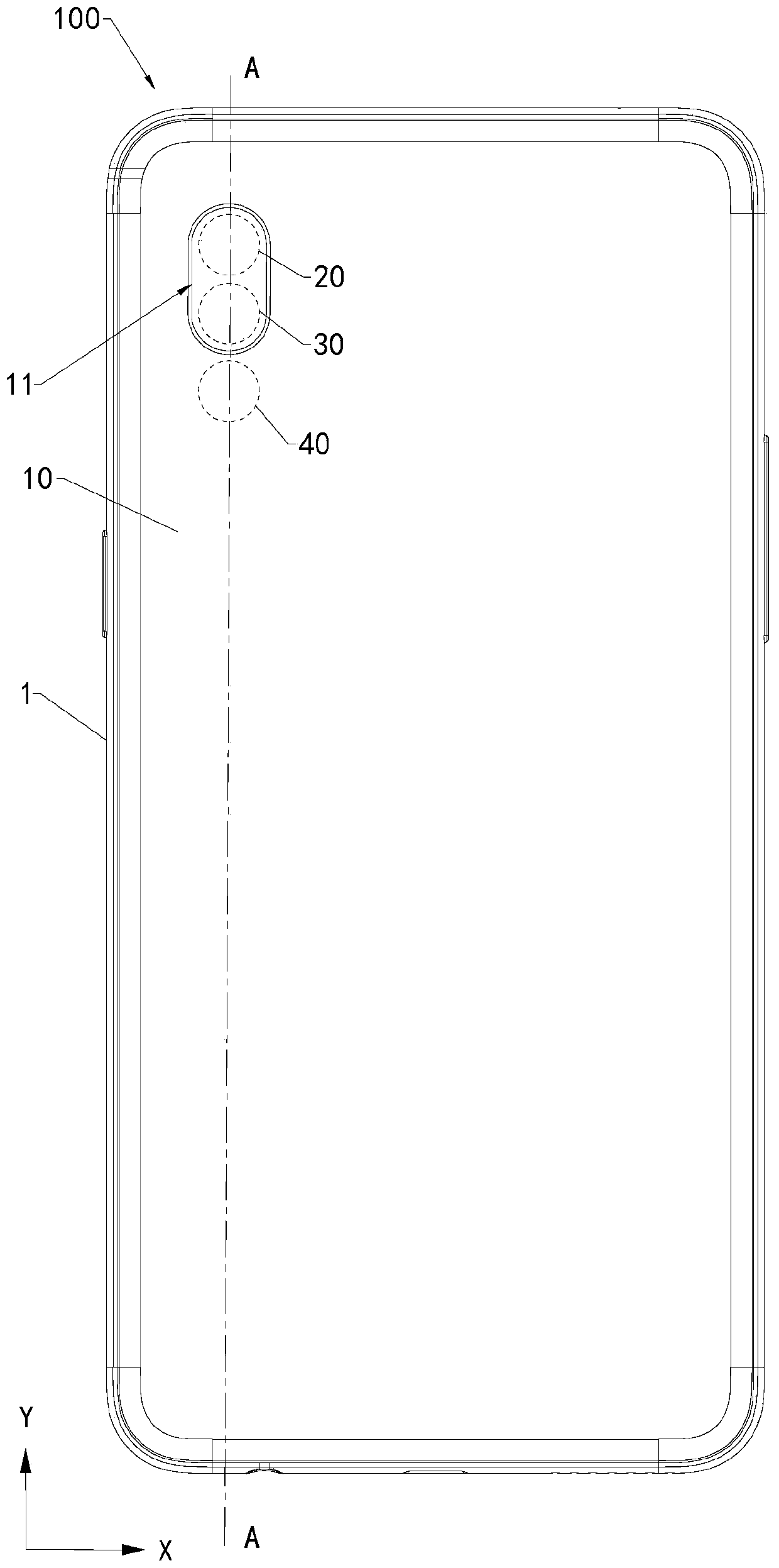
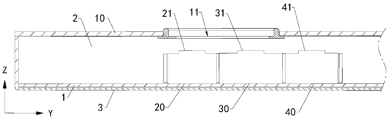
[0048] Implementation mode one: if Figure 9 As shown, the rear cover 10 includes a rear cover body 12 and a camera decoration 13 . The rear cover body 12 is connected to the middle frame 1 . The rear cover body 12 defines a light-transmitting through hole 121 . The camera head decoration 13 surrounds the light-transmitting through hole 121 . It can be understood that the peripheral edge of the camera decoration 13 is bonded to the back cover body 12 by glue, so as to prevent external water vapor or dust from entering the storage space 2 from the gap between the camera decoration 13 and the back cover body 12 . The light-transmitting part 11 is located on the camera head decoration 13 . The first camera 20 , the second camera 30 and the third camera 40 are all slidably connected to the middle frame 1 . It can be understood that when the first camera 20, the second camera 30 and the third camera 40 are slidably connected to the middle frame 1, the first camera 20 can slide...

Embodiment approach 2

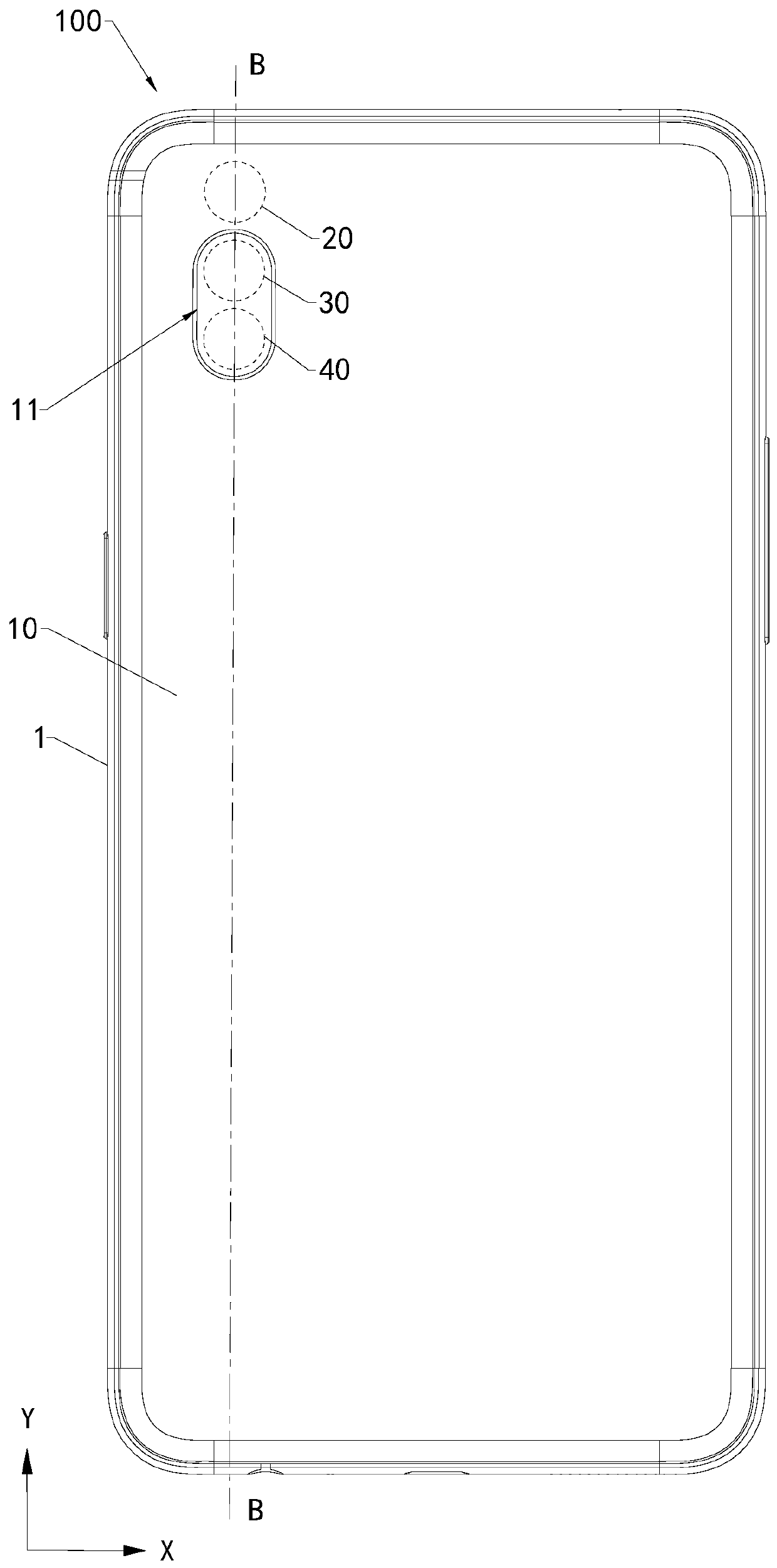
[0059] Embodiment 2, most of the same technical content as Embodiment 1 will not be repeated here: For example Figure 13 As shown, the rear cover 10 includes a rear cover body 12 and a camera decoration 13 . The rear cover body 12 is connected to the middle frame 1 . The light-transmitting portion 11 is disposed on the camera decoration 13 . The camera decoration 13 is movably connected to the rear cover body 12, so that the light-transmitting part 11 is facing the photosensitive surface 21 of the first camera 20 and the photosensitive surface of the second camera 30 or the light-transmitting part 11 is facing the photosensitive surface 31 of the second camera 30 Or the photosensitive surface 41 of the third camera 40 . Optionally, the camera head decoration 13 is provided with a first slide groove 139 , and the rear cover body 12 is provided with a first slider 128 . The extension direction of the first slide slot 139 is parallel to the length direction of the electronic ...


PUM


Abstract

The invention discloses electronic equipment and a shooting method of the electronic equipment. Electronic equipment comprises a middle frame, a Rear cover, a first camera, a Second camera and a thirdcamera; the rear cover covers the middle frame so as to form a Containing space, The rear cover is provided with a light-transmitting part; the First camera, the second camera and the third camera are arranged in the accommodating space; the First camera, the second camera and the third camera are movably connected to the middle frameand are opposite to or far away from the light-transmitting part; When the electronic equipment is switched to the first shooting mode, the photosensitive surface of the first camera and the photosensitive surface of the second camera are opposite to the light transmitting part, and when the electronic equipment is switched to the second shooting mode and the photosensitive surface of the second camera and the photosensitive surface of the third camera are opposite to the light transmitting part, the first shooting mode is different from the second shooting mode. The electronic device is good in appearance consistency.

Description

technical field [0001] The present application relates to the technical field of electronic equipment, and in particular to an electronic equipment and a photographing method of the electronic equipment. Background technique [0002] With the development of electronic device technology, more and more electronic devices integrate more and more cameras. However, as the number of cameras increases, the light transmission holes on the back cover of the electronic device become larger and larger, which makes the appearance consistency of the back cover of the electronic device worse and worse, which cannot meet the needs of users, that is, reduces the user experience. Contents of the invention [0003] The present application provides an electronic device and a photographing method of the electronic device, and the electronic device has better appearance consistency. [0004] An embodiment of the present application provides an electronic device. The electronic device includ...

Claims


Application Information

Patent Timeline
Patent Type & Authority Applications(China)
IPC IPC(8): H04M1/02H04N5/225H04N5/232H04N5/235H04N5/247
Inventor 姚坤
Owner GUANGDONG OPPO MOBILE TELECOMM CORP LTD
Why Eureka
Try Eureka