Optical fiber installation device and vehicle lamp assembly system

A technology for installing equipment and optical fibers, which is applied in the fields of optical fiber installation equipment and car light assembly systems, can solve problems such as difficulties in installing and fixing optical fibers, and achieve the effects of good appearance consistency, high intelligence, and improved yield

Pending Publication Date: 2018-09-07
HASCO VISION TECHNOLOGY CO LTD
View PDF0 Cites 4 Cited by
  • Summary
  • Abstract
  • Description
  • Claims
  • Application Information

AI Technical Summary

Problems solved by technology

[0005] The purpose of the present invention is to provide an optical fiber installation device to solve the technical problem of difficult installation and fixation of optical fibers in the prior art

Method used


Image

  • Optical fiber installation device and vehicle lamp assembly system
  • Optical fiber installation device and vehicle lamp assembly system
  • Optical fiber installation device and vehicle lamp assembly system

Examples


Embodiment 1

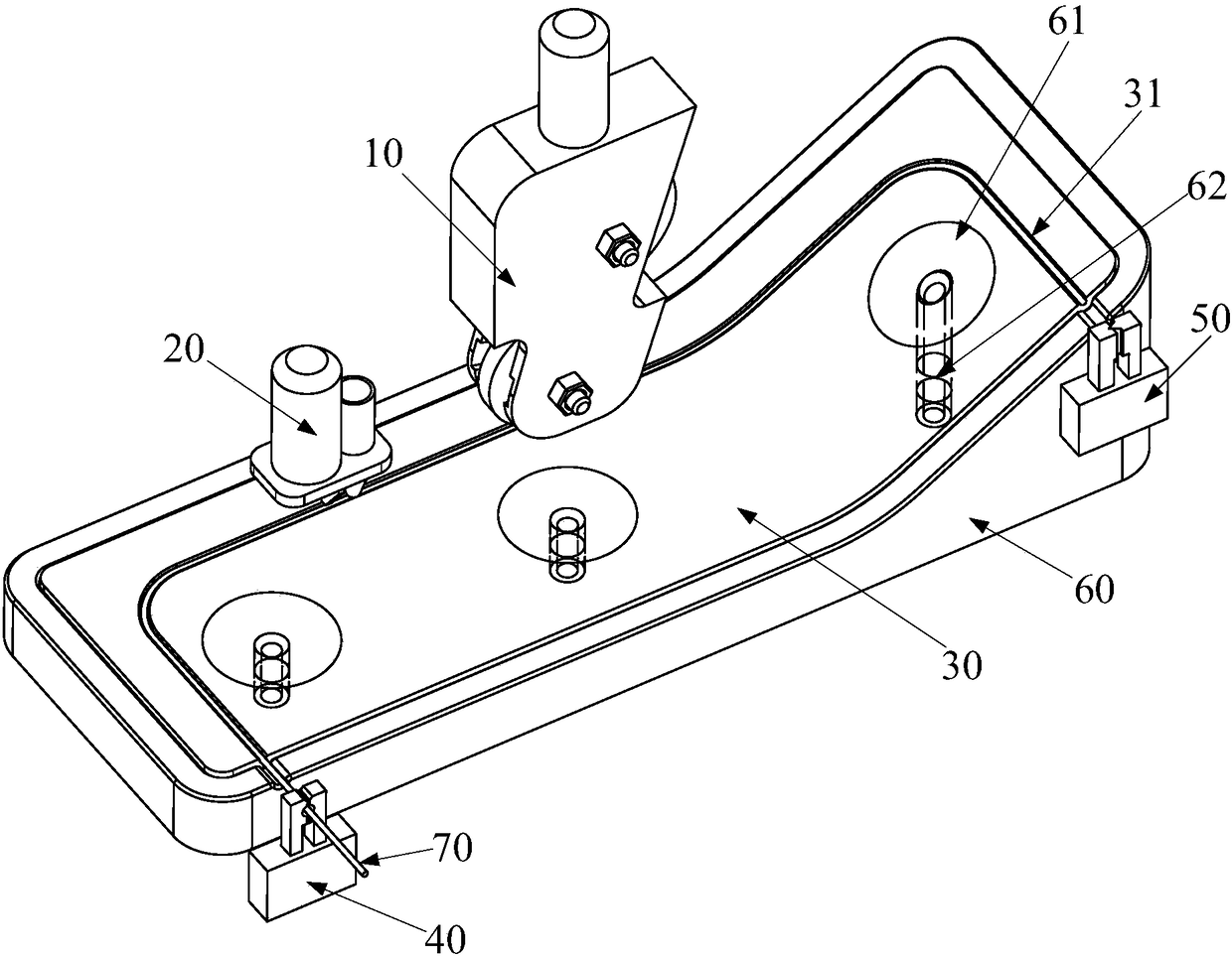
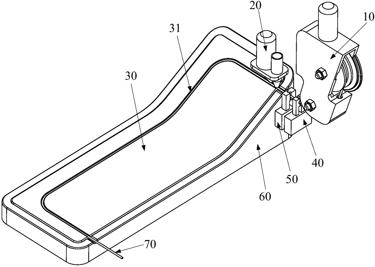
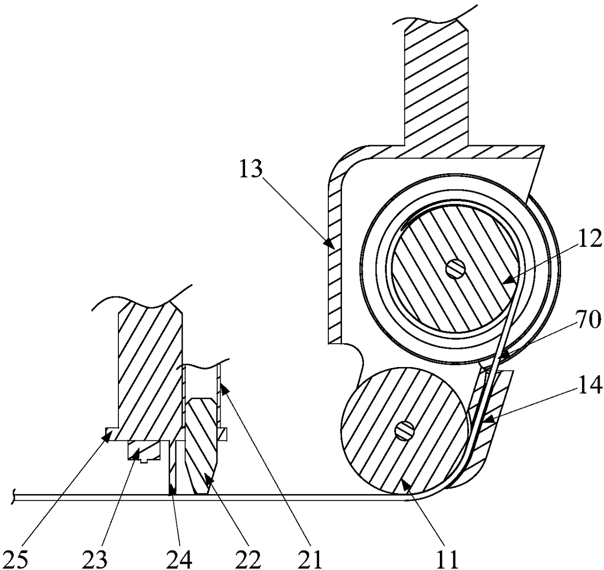
[0036] Such as Figure 1-Figure 4 As shown, the optical fiber 70 installation equipment provided by the embodiment of the present invention includes: a laying mechanism 10, a glue application mechanism 20, and a driving mechanism. The mechanism is respectively connected with the laying mechanism 10 and the gluing mechanism 20 to drive the laying mechanism 10 and the gluing mechanism 20 to move along the optical fiber placement groove 31. The laying mechanism 10 is used to place the optical fiber 70 in the optical fiber placement groove 31, and the gluing mechanism 20 It is used to apply glue to the optical fiber 70 located in the optical fiber arranging groove 31 so that the optical fiber 70 is fixed in the optical fiber arranging groove 31 .

[0037] The optical fiber 70 installation device of the embodiment of the present invention is used to install the optical fiber 70 on the optical fiber fixing carrier 30, and the optical fiber fixing carrier 30 is the internal fittings,...

Embodiment 2

[0061] Embodiment 2 of the present invention provides a vehicle lamp assembly system, including the optical fiber installation device provided in Embodiment 1 above. The optical fiber installation equipment is used to install the optical fiber to the optical fiber fixed carrier. In addition, the car light assembly system can also include light source installation equipment, reflector installation equipment, overall assembly equipment, etc.

[0062] The vehicle lamp assembly system has the same advantages as the optical fiber installation device provided in the first embodiment above compared with the prior art, and will not be repeated here.


PUM


Abstract

The invention provides an optical fiber installation device and a vehicle lamp assembly system, relates to the technical field of vehicle lamp assembly systems and aims to solve the problem of difficult mounting and fixing of optical fibers. The optical fiber installation device comprises a laying mechanism, a gluing mechanism and a driving mechanism, wherein the optical fiber is arranged in the laying mechanism, an optical fiber placing groove is arranged on the optical fiber fixing carrier, the driving mechanism is respectively connected with the laying mechanism and the gluing mechanism todrive the laying mechanism and the gluing mechanism to move along the optical fiber placing groove, and the laying mechanism is used for placing the optical fiber in the optical fiber placing groove.The optical fiber installation device is used for installing the optical fiber into the optical fiber fixing carrier, and fixing the optical fiber in the optical fiber fixing carrier through the glueliquid. The device has the advantages of high efficiency, small manual labor amount, high yield, high reliability and good appearance consistency, and the fiber track can be space three-dimensional.

Description

technical field [0001] The invention relates to the technical field of vehicle light assembly systems, in particular to an optical fiber installation device and a vehicle light assembly system. Background technique [0002] At present, optical fibers are used as light guide carriers in some car lights. The optical fiber is made of glass or plastic, which can be used as the carrier of light transmission in the car lamp and play a lighting role. When in use, fix the optical fiber to the internal parts of the car light to realize its installation relative to the car light. A laser or LED used as a light source can be coupled to one end of the fiber in advance (or after the fiber is fixed), and the fiber can be ignited after being powered on. [0003] Optical fibers are used as lighting and decorative parts in car lights. After fixing, most areas can be seen in appearance, and there should be no installation structure that affects the appearance; Two-dimensional planar area, ...

Claims


Application Information

Patent Timeline
Patent Type & Authority Applications(China)
IPC IPC(8): G02B6/46
CPCG02B6/46
Inventor 杨珏晶周浩陈虎王良亮
Owner HASCO VISION TECHNOLOGY CO LTD
Why Eureka
Try Eureka