Supercharge Your Innovation With Domain-Expert AI Agents!

Machining device and machining method

A technology for equipment and workpieces, applied in metal processing equipment, grinding/polishing equipment, manufacturing tools, etc., can solve problems such as changes in pressing force at the workpiece, and achieve the effect of reducing weight, simplifying installation, and improving operating characteristics

Pending Publication Date: 2019-05-03
HOMAG BOHRSYST GMBH
View PDF7 Cites 1 Cited by
  • Summary
  • Abstract
  • Description
  • Claims
  • Application Information

AI Technical Summary

Problems solved by technology

[0003] However, if, for example, a workpiece having a height difference above the machining path is machined, the pressing force at the workpiece changes

Method used


Image

  • Machining device and machining method
  • Machining device and machining method
  • Machining device and machining method

Examples


Embodiment Construction

[0043] A preferred embodiment of the present invention is described below with reference to the accompanying drawings. Other variants mentioned in this context of specific individual features can each be individually combined with one another in order to form new embodiments.

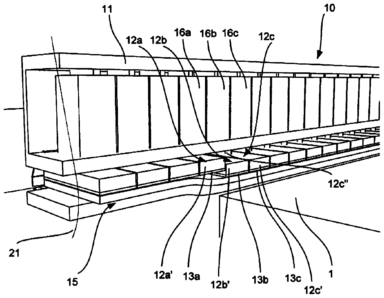
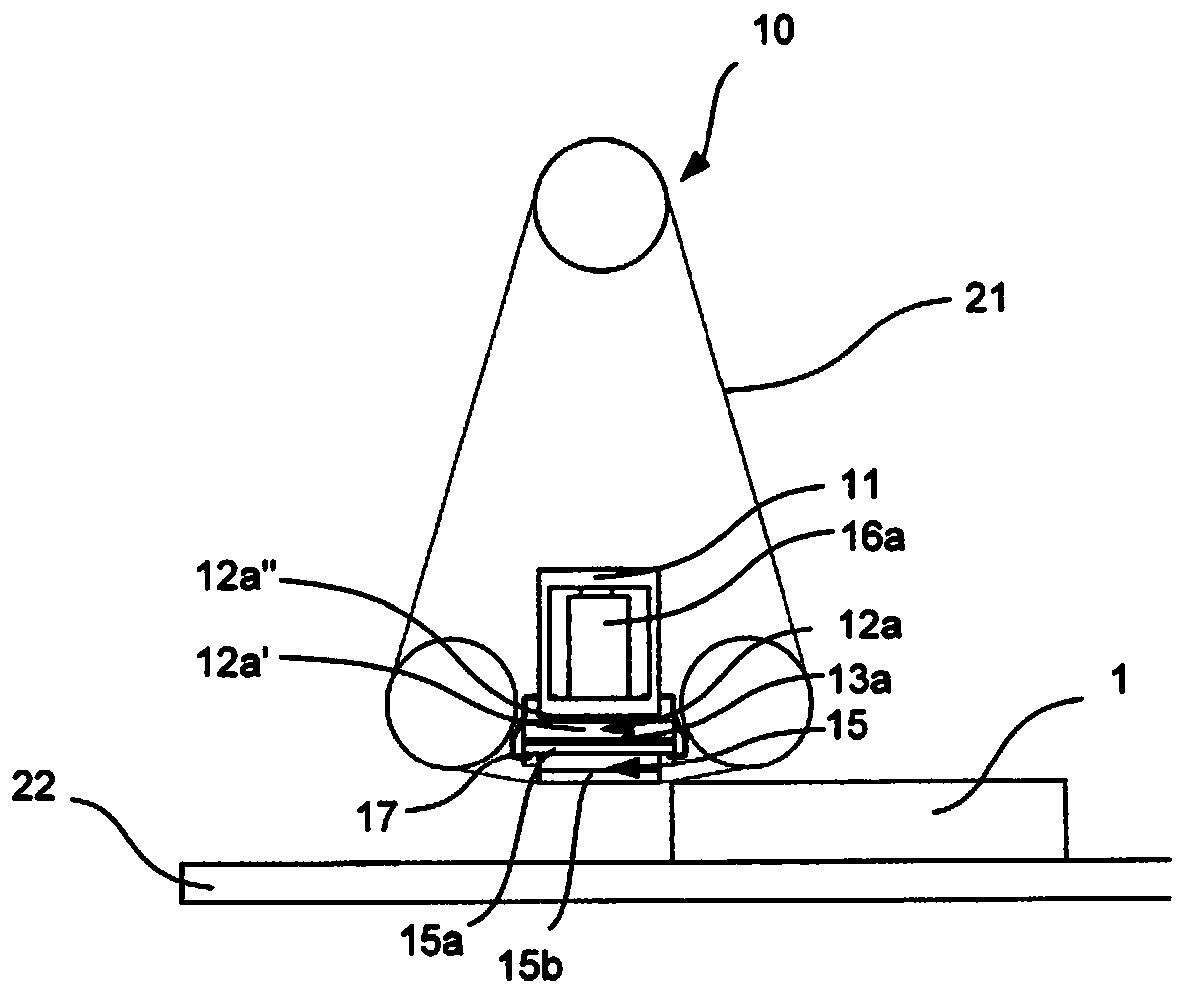
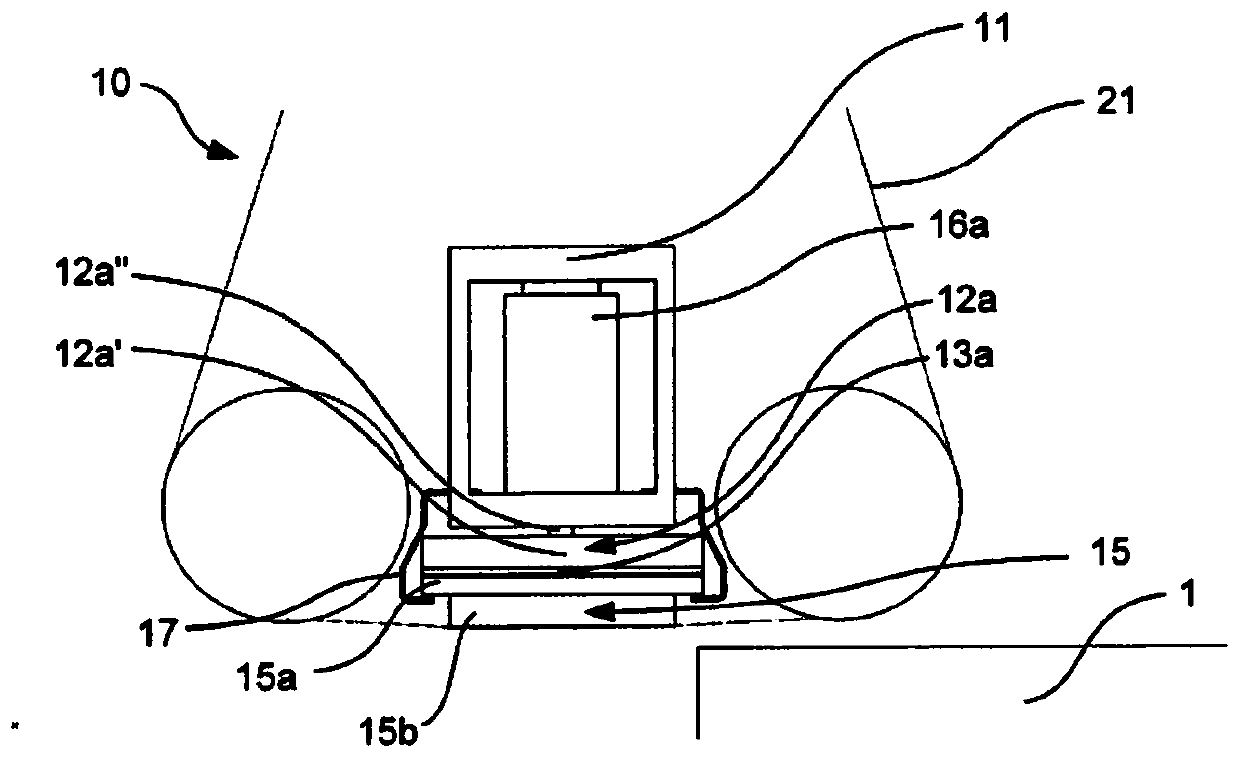
[0044] figure 1 A detailed view of the device 10 is shown, which in the embodiment explained here is a sanding unit of a wide-band sander. A perspective view of a broadband sander capable of accommodating multiple sanding units is depicted in Figure 3. It can be seen that the device 10 can also be used in a belt sander.

[0045] The device 10 comprises a carrier element 11 which is figure 1 -Extends above the machine tool not shown in detail in -2. The carrier element 11 is in the belt sander image 3 It extends within the housing shown in and transversely to the conveying path of the workpiece. In particular, the workpieces 1 can be moved by means of a preferably circumferential conveyor belt 22 ...


PUM


Abstract

The present invention relates to a device for sanding surfaces of a workpiece, preferably at least portions of which are made of wood, a manufactured wood product, plastic, or such like. The inventionfurther relates to a sanding machine and a method.

Description

technical field [0001] The invention relates to a device for sanding the surface of workpieces, which preferably consist at least in sections of wood, wood-based panels, plastic or the like. Furthermore, the invention relates to a sander and a method. Background technique [0002] In the prior art, sanding machines comprise a carrier element which has carrier element sections, the latter being individually adjustable in order to press the sanding belt against a section of the workpiece to be processed. The deployment movement of the carrier element segments is initiated by a control device to which information about the workpiece is fed. [0003] However, if, for example, a workpiece with a height difference over the machining path is machined, the pressing force at the workpiece changes. This can lead to different sanding results within certain, defined thickness tolerances. Contents of the invention [0004] It is an object of the present invention to provide a device...

Claims


Application Information

Patent Timeline
IPC IPC(8): B24B21/06B24B49/16B24B21/18B24B21/08
CPCB24B49/16B24B21/08B24B21/10B24B49/10
Inventor 托马斯·贝特尔曼
Owner HOMAG BOHRSYST GMBH
Features
  • R&D
  • Intellectual Property
  • Life Sciences
  • Materials
  • Tech Scout
  • Unparalleled Data Quality
  • Higher Quality Content
  • 60% Fewer Hallucinations
Learn More