
Braking device and mechanical facility

A technology of braking device and magnetic conductive element, which is applied in mechanical equipment, braking actuator, gear shifting mechanism, etc., can solve the problem of longer braking (braking) time and so on.

Pending Publication Date: 2019-05-07
SHENZHEN ZHAOWEI MACHINERY&ELECTRONICS CO LTD
View PDF13 Cites 0 Cited by
  • Summary
  • Abstract
  • Description
  • Claims
  • Application Information

AI Technical Summary

Problems solved by technology

After the motor stops, the counter-driving force will drive the output shaft of the motor to continue to rotate, which in turn will cause the braking (braking) time of the motor to become longer

Method used


Image

  • Braking device and mechanical facility
  • Braking device and mechanical facility
  • Braking device and mechanical facility

Examples


Embodiment 1

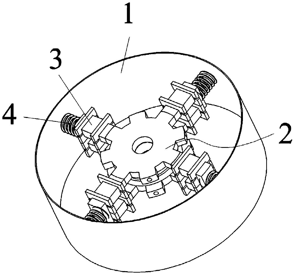
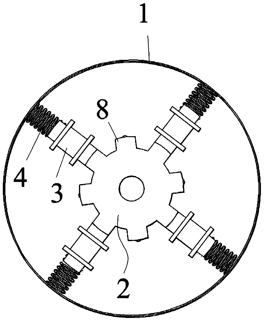
[0041] refer to figure 1 and figure 2 , in this embodiment, a brake device is proposed, including a housing 1 and a magnetic assembly 2 for connecting to a drive shaft of a motor and having magnetism. The magnetic assembly 2 is located inside the housing 1 .

[0042] A braking magnetic conductor 3 for braking the magnetic assembly 2 is disposed inside the housing 1 . Wherein, the brake magnetic permeable part 3 is wound with a coil for making the brake magnetic permeable part 3 generate repulsive magnetism with the magnetic component 2 through energization. Wherein, a wire clip or a wire slot for winding the coil may be provided on the brake magnetic guide 3 .

[0043] The brake magnetic guide 3 is movably arranged between the shell 1 and the magnetic assembly 2 . The brake magnetic guide 3 is in contact with or separated from the magnetic assembly 2 through the force of the magnetic field.

[0044] In this embodiment, the inside of the housing 1 is a hollow structure, an...


PUM


Abstract

The invention discloses a braking device and a mechanical facility. The braking device comprises a shell and a magnetic assembly, wherein the magnetic assembly is used for being connected with a driving shaft of a motor and located inside the shell. Braking magnetism conducting parts which are used for braking the magnetic assembly are arranged in the shell. Coils which are used for enabling the braking magnetism conducting parts to generate the magnetism repelling the magnetism of the magnetic assembly through energization are wound around the braking magnetism conducting parts. The braking magnetism conducting parts are movably arranged between the shell and the magnetic assembly and make contact with the magnetic assembly through the magnetic field force or repel the magnetic assembly through the magnetic field force. The braking device has a self-locking function and can achieve rapid braking of the motor.

Description

technical field [0001] The invention relates to the technical field of brakes, in particular to a brake device and mechanical equipment. Background technique [0002] In the field of mechanical transmission, motors are mostly used for transmission. [0003] In the process of transmission, there will be a counter-driving force, which may come from loads, inertial forces, etc. After the motor stops, the counter-driving force will drive the output shaft of the motor to continue to rotate, which in turn will cause the braking (braking) time of the motor to become longer. Contents of the invention [0004] The purpose of the present invention is to overcome the defects of the prior art and provide a brake device and mechanical equipment. [0005] In order to solve the above problems, the present invention provides: a brake device, comprising a housing and a magnetic assembly for connecting to a drive shaft of a motor and having magnetism, the magnetic assembly is located insi...

Claims


Application Information

Patent Timeline
Patent Type & Authority Applications(China)
IPC IPC(8): F16D49/18F16D65/14F16D121/22
Inventor 叶曙兵谢伟群霍卫红柯善垚
Owner SHENZHEN ZHAOWEI MACHINERY&ELECTRONICS CO LTD
Learn More