Heat exchangers, heat exchange systems and air conditioners

A heat exchanger and refrigerant system technology, which is applied in evaporator/condenser, refrigeration and liquefaction, lighting and heating equipment, etc., can solve the problems of large temperature difference of the outlet air of the refrigerant circuit, low heat transfer efficiency, bypass, etc. Achieve uniform air temperature and high heat exchange efficiency

Active Publication Date: 2022-02-25
SANHUA(HANGZHOU) MICRO CHANNEL HEAT EXCHANGER CO LTD
View PDF10 Cites 0 Cited by
  • Summary
  • Abstract
  • Description
  • Claims
  • Application Information

AI Technical Summary

Problems solved by technology

[0003] However, multiple refrigerant circuits share one fan. When the whole machine is running at partial load, assuming that only one refrigerant circuit is running, since multiple refrigerant circuits are relatively independent, only this refrigerant circuit has refrigerant flow, while other non-operating There is no refrigerant flow in the refrigerant circuit, which causes the air volume of other refrigerant circuits to be bypassed and not participate in heat exchange. The overall effective utilization rate of the heat exchanger is low, the heat exchange efficiency is low, and the temperature difference of the air outlet of multiple refrigerant circuits is large. Exhaust air temperature is very uneven

Method used


Image

  • Heat exchangers, heat exchange systems and air conditioners
  • Heat exchangers, heat exchange systems and air conditioners
  • Heat exchangers, heat exchange systems and air conditioners

Examples


Embodiment Construction

[0041] Embodiments of the present invention are described in detail below, examples of which are shown in the drawings, wherein the same or similar reference numerals designate the same or similar elements or elements having the same or similar functions throughout. The embodiments described below by referring to the figures are exemplary only for explaining the present invention and should not be construed as limiting the present invention.

[0042] In describing the present invention, it is to be understood that the terms "length", "width", "thickness", "upper", "lower", "left", "right", "inner", "outer" etc. indicate The orientation or positional relationship is based on the orientation or positional relationship shown in the drawings, and is only for the convenience of describing the present invention and simplifying the description, rather than indicating or implying that the referred device or element must have a specific orientation or be configured in a specific orienta...


PUM


Abstract

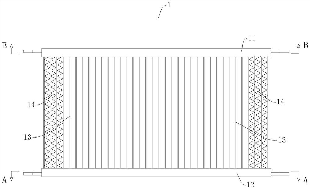
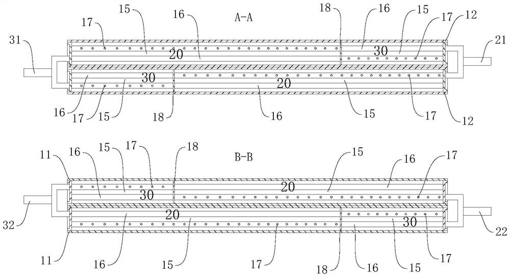
The invention discloses a heat exchanger, a heat exchange system and an air conditioner. The heat exchanger includes multiple rows of sub-heat exchangers, and the multiple rows of sub-heat exchangers are arranged along the thickness direction of the sub-heat exchangers and parallel to each other. , the heat exchanger has a plurality of refrigerant systems, and each of the refrigerant systems is distributed on at least two rows of sub-heat exchangers; wherein, in a plane perpendicular to the thickness direction of the sub-heat exchangers, the same refrigerant The projections of the parts of the system on any two rows of sub-heat exchangers are at least partially non-overlapping. The heat exchanger according to the embodiment of the present invention is suitable for multi-refrigerant circuits, and has the advantages of high heat exchange efficiency, uniform outlet air temperature, and the like.

Description

technical field [0001] The invention relates to the technical field of heat exchange, in particular, to a heat exchanger, a heat exchange system with the heat exchanger, and an air conditioner with the heat exchange system. Background technique [0002] In the related art, some air conditioners such as commercial air conditioners use multiple refrigerant circuits. Taking dual refrigerant circuits as an example, under low load, a certain refrigerant circuit can be controlled to stop to adapt to load changes and provide better operating efficiency. [0003] However, multiple refrigerant circuits share one fan. When the whole machine is running at partial load, assuming that only one refrigerant circuit is running, since the multiple refrigerant circuits are relatively independent, only this refrigerant circuit has refrigerant flow, while other non-operating There is no refrigerant flow in the refrigerant circuit, which causes the air volume of other refrigerant circuits to be...

Claims


Application Information

Patent Timeline
Patent Type & Authority Patents(China)
IPC IPC(8): F25B39/00
Inventor 冯伟红
Owner SANHUA(HANGZHOU) MICRO CHANNEL HEAT EXCHANGER CO LTD
Why Eureka
Try Eureka