Supercharge Your Innovation With Domain-Expert AI Agents!

Stator and rotor press-fitting device

A press-fitting device and stator technology, which is used in the manufacture of stator/rotor body, centering/balancing rotor, metal processing, etc., can solve the problem of long press-fitting time, high noise, and difficulty in ensuring the coaxiality of the stator, rotor and end cover. and other problems, to achieve the effect of good pressing effect and high pressing efficiency.

Pending Publication Date: 2019-05-07
ZHEJIANG LINIX MOTOR
View PDF11 Cites 6 Cited by
  • Summary
  • Abstract
  • Description
  • Claims
  • Application Information

AI Technical Summary

Problems solved by technology

[0002] Some motors use the stator as the motor casing, which needs to be assembled between the stator, the rotor and the end cover. The two ends of the rotor shaft of the rotor need to be pressed with the stator bearing and the end cover bearing respectively; The magnetic attraction force is very large, and the rotor is often adsorbed on the inner wall of the stator to make the rotor shaft tilt. The press-fitted rotor has problems of difficult rotation and high noise; and in the prior art, the press-fitting at both ends of the rotor shaft is carried out separately It takes a long time to press and install, and it is difficult to ensure the coaxiality among the stator, rotor and end cover

Method used


Image

  • Stator and rotor press-fitting device
  • Stator and rotor press-fitting device
  • Stator and rotor press-fitting device

Examples


Embodiment Construction

[0017] The present invention will be further described below according to the accompanying drawings and specific embodiments.

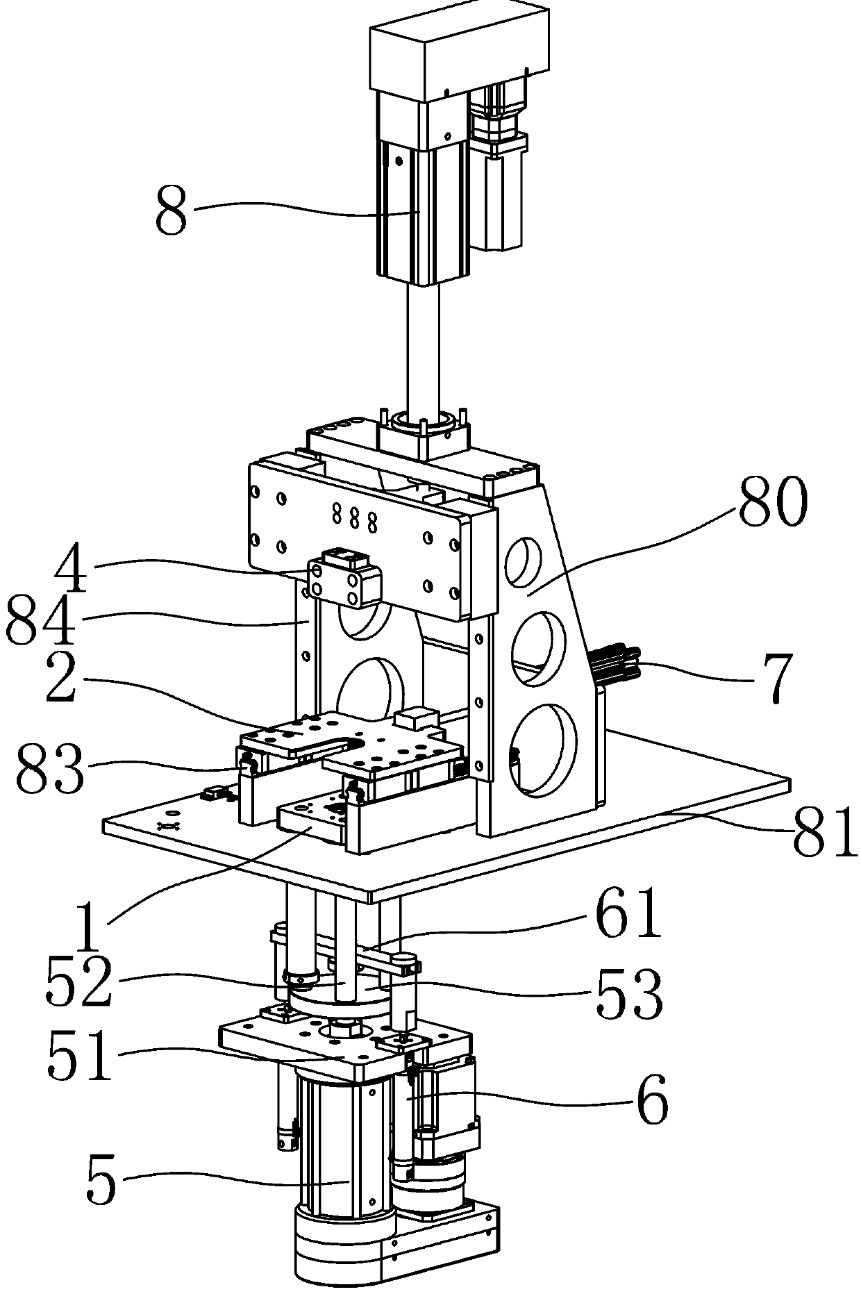
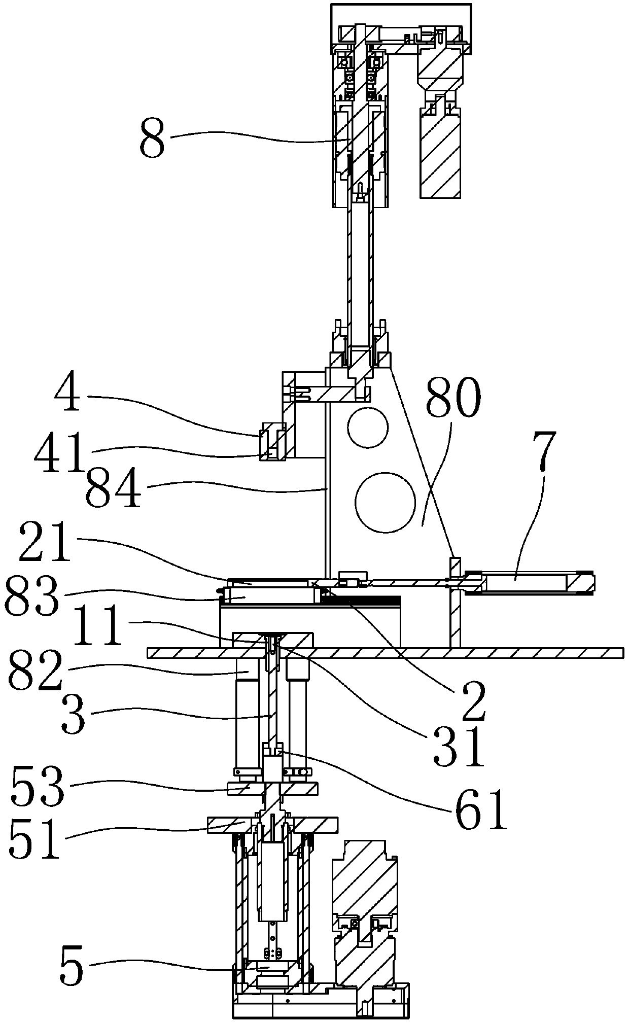
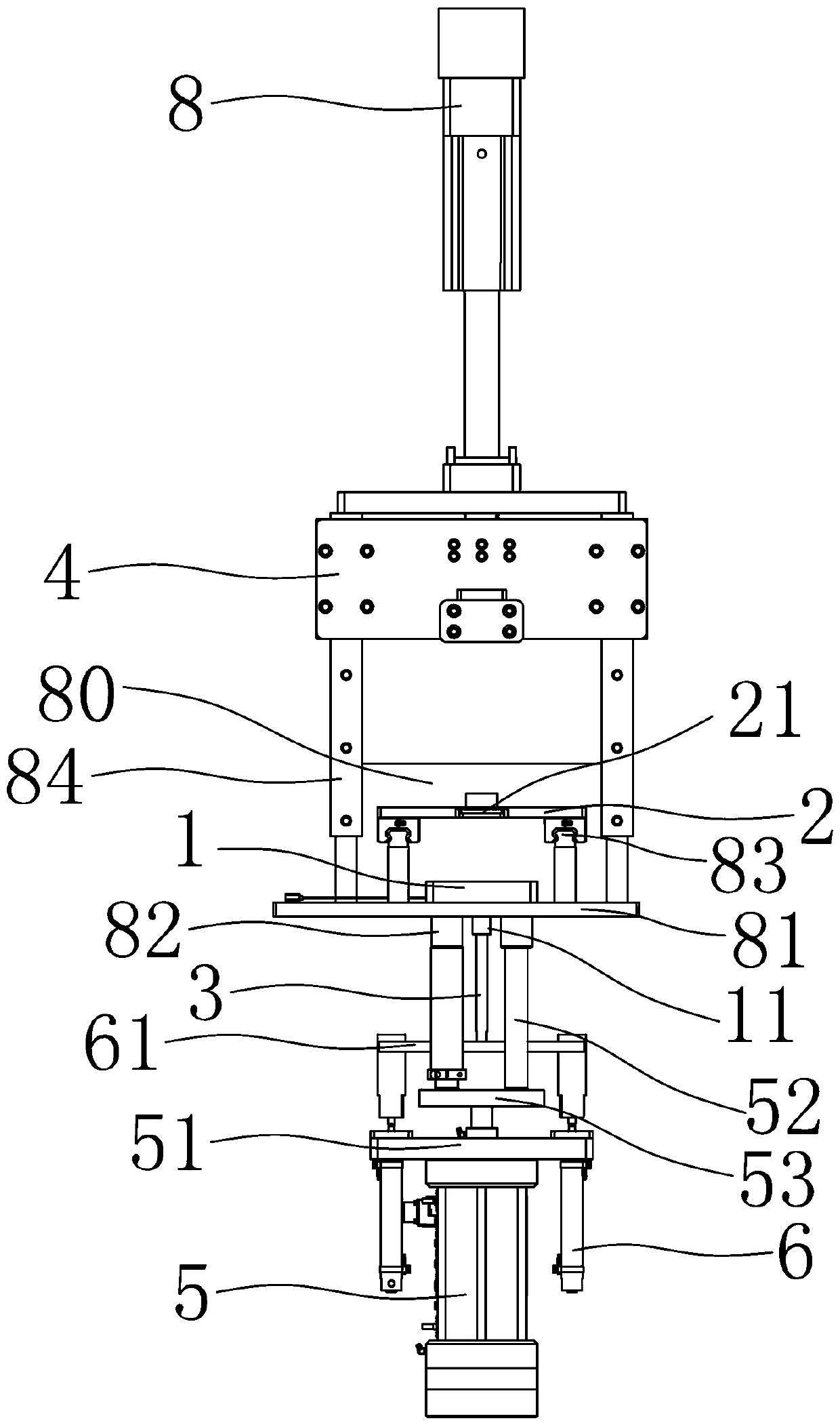
[0018] Depend on figure 1 , figure 2 , image 3 As shown, a stator and rotor pressing device of the present invention includes a positioning plate 1, a limiting plate 2, a movable rod 3, a pressing block 4, a first lifting device 5, a second lifting device 6, a linear motion device 7 and Press machine 8, press machine 8 is fixed on the upper fixed plate 81 by support 80, the first lifting device 5 and the second lifting device 6 are arranged on the lower side of the upper fixed plate 81, and the first lifting device 5 is fixed on the lower fixed plate (Fig. not shown in).

[0019] The movable rod 3 is vertically arranged, the positioning plate 1 and the limit plate 2 are used for positioning and fixing the stator, the first lifting device 5 is used to control the movement of the positioning plate 1 up and down, and the second lifting device 6 is u...


PUM


Abstract

The invention aims to provide a stator and rotor press-fitting device which is better in press-fitting effect and higher in press-fitting efficiency. The stator and rotor press-fitting device comprises a positioning plate, a limiting plate, a movable rod, a first lifting device, a second lifting device, a linear motion device and a pressing machine, wherein the first lifting device is used for controlling the up-and-down movement of the positioning plate, the second lifting device is used for controlling the up-and-down movement of the movable rod, the linear motion device is used for controlling the back-and-forth movement of the limiting plate, the pressing machine is used for controlling the up-and-down movement of a pressing block, the positioning plate moves upward so as to clamp a stator between the positioning plate and the limiting plate, the positioning plate is provided with a first through hole which vertically runs through so as to enable the movable rod to pass through, the limiting plate is provided with an open slot which vertically runs through and is provided with a forward opening so as to enable an upper end of the movable rod to pass through, the movable rod isprovided with a lower positioning hole matched with the lower end of a rotor shaft, the pressing block is provided with an upper positioning hole matched with the upper end of the rotor shaft, and theupper positioning hole and the lower positioning hole are coaxially arranged.

Description

technical field [0001] The invention relates to a device for assembling a motor, in particular to a press-fitting device for a stator and a rotor. Background technique [0002] Some motors use the stator as the motor casing, which needs to be assembled between the stator, the rotor and the end cover. The magnetic attraction force is very large, and the rotor is often adsorbed on the inner wall of the stator to make the rotor shaft tilt. The press-fitted rotor has problems of difficult rotation and high noise; and in the prior art, the press-fitting at both ends of the rotor shaft is carried out separately However, it takes a long time to press and install, and it is difficult to ensure the coaxiality among the stator, rotor and end cover. Contents of the invention [0003] The purpose of the present invention is to provide a stator and rotor press-fitting device with better press-fit effect and higher press-fit efficiency. [0004] In order to achieve the above object, t...

Claims


Application Information

Patent Timeline
Patent Type & Authority Applications(China)
IPC IPC(8): H02K15/16
CPCH02K15/16Y02T10/64B23P19/027B23P19/006H02K15/02
Inventor 任秉文郭刚浩陶广旭孙祝兵
Owner ZHEJIANG LINIX MOTOR
Features
  • R&D
  • Intellectual Property
  • Life Sciences
  • Materials
  • Tech Scout
  • Unparalleled Data Quality
  • Higher Quality Content
  • 60% Fewer Hallucinations
Learn More