Bipolar electric coagulation forceps with time delay switch

A technology of time-delay switch and electrocoagulation forceps, applied in the field of medical devices, can solve the problems of heat loss of insulating parts, reduce the speed and effect of electrocoagulation, inconvenience of carrying and use of bipolar electrocoagulation forceps, etc. Moderate volume, no damage effect

Pending Publication Date: 2019-05-10
HANGZHOU KANGJI MEDICAL INSTR
View PDF1 Cites 0 Cited by
  • Summary
  • Abstract
  • Description
  • Claims
  • Application Information

AI Technical Summary

Benefits of technology

This new type of electric coaguage instrument has two main benefits compared to previous instruments - it's smaller size but more effective at treating blood clots than older ones-and its ability for multiple uses without damaging any parts or components inside them. It also allows for quicker treatment times while still producing high levels of efficacy.

Problems solved by technology

This patented technical problem addressed in this patents relates to improving the performance of an electric catheterization (ECC) forcep tool system while reducing weight and volume compared to older methods like manual control tools. Existing designs require bulky power supplies and may result in longer operating times due to increased energy consumption. Therefore, new proposals aim to provide better design options based on these factors.

Method used


Image

  • Bipolar electric coagulation forceps with time delay switch
  • Bipolar electric coagulation forceps with time delay switch
  • Bipolar electric coagulation forceps with time delay switch

Examples


Embodiment 1

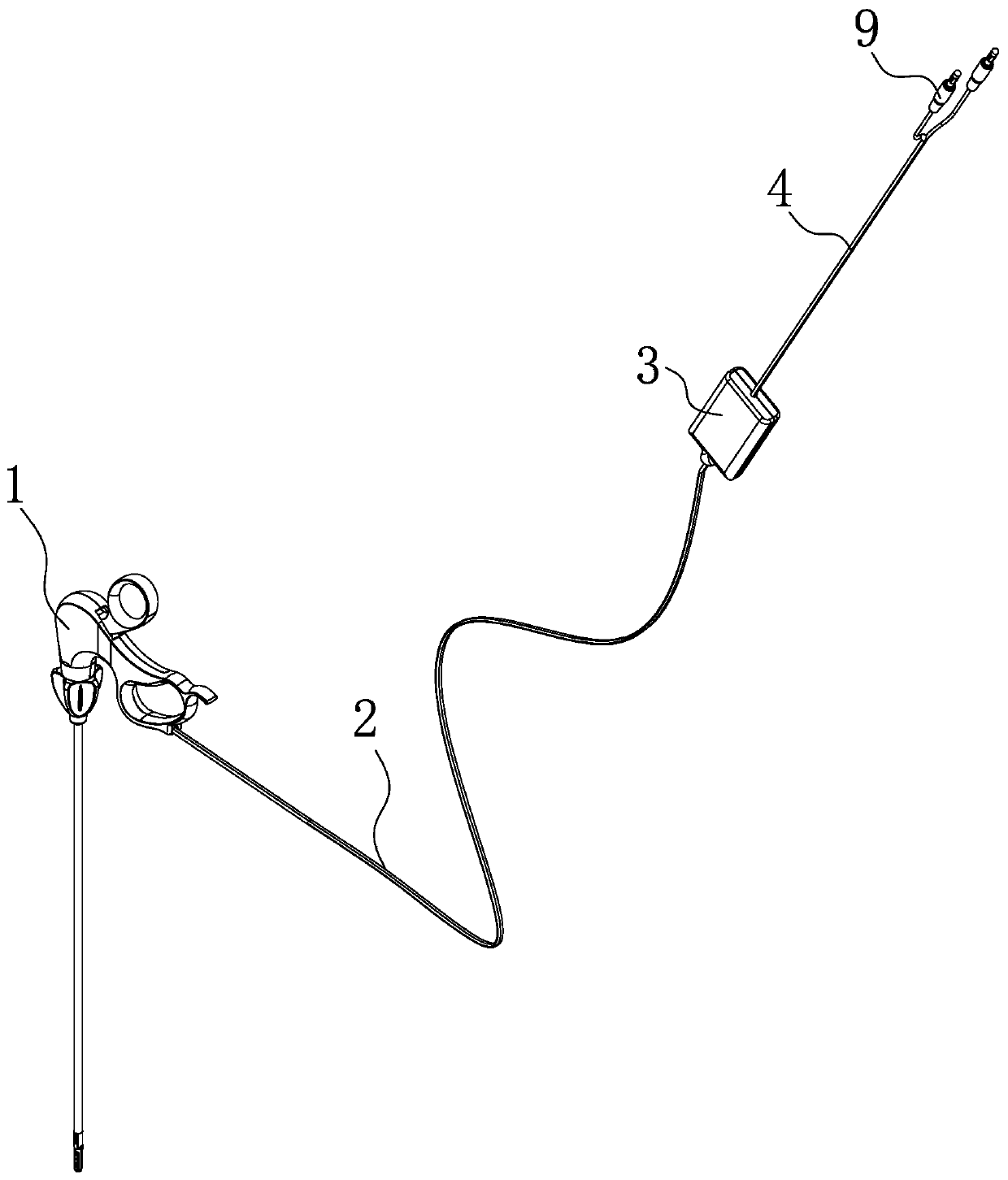
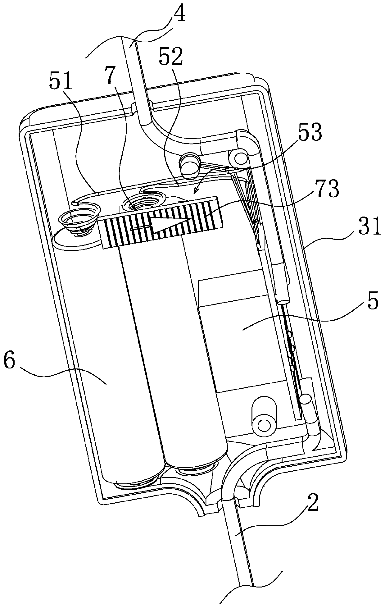
[0025] like Figure 1-5 As shown, the bipolar coagulation forceps with a delay switch includes a main body 1 of the coagulation forceps, the main body 1 of the forceps is connected with an energy supply line 2 of the forceps, and the energy supply line 2 of the forceps passes through the electric coagulation switch 3 and The electrocoagulation forceps energy supply connection line 4 connected to the energy supply end of the electrocoagulation forceps is connected, the electrocoagulation switch 3 has a delay relay 5, and one end of the delay relay 5 is connected to the power supply line 2 of the electrocoagulation forceps, and the delay relay 5 is connected to the other end. One end is connected to the power supply connection line 4 of the electrocoagulation forceps, and the delay relay 5 is connected to the switch power supply module 6, and a switch for controlling the switch power supply module 6 and the delay relay 5 is provided between the switch power supply module 6 and th...

Embodiment 2

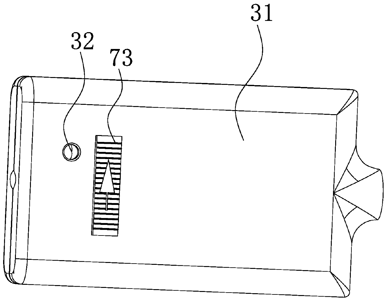
[0037]The structure, principle and implementation steps of this embodiment are similar to those of Embodiment 1, the difference lies in that one of the two box halves in this embodiment has a plurality of positioning grooves, and the other box half has a plurality of positioning grooves. There is a positioning post corresponding to the positioning slot, and the positioning post and the positioning slot are clamped so that the switch box body 31 is in a closed state, and the positioning post is provided with a clamping slot, the electrocoagulation forceps power supply line 2, the electrocoagulation forceps power supply The connection line 4, the first lead wire 51 and the second lead wire 52 are all arranged in the wire clamping groove, and when the switch box body 31 is forcibly disassembled, various energy supply lines will be pulled off, so that the electrocoagulation forceps can no longer conduct the power supply , completely make the electrocoagulation forceps disposable el...


PUM


Abstract

The invention relates to a pair of bipolar electric coagulation forceps with a time delay switch. The problems that bipolar electric coagulation forceps are inconvenient to carry, the electric coagulation speed is low, and the electric coagulation effect is poor are solved. The bipolar electric coagulation forceps comprise an electric coagulation forceps main body, an electric coagulation forcepsenergy supply line is connected to the electric coagulation forceps main body, and connected with an electric coagulation forceps energy supply connecting line which is connected with an electric coagulation forceps energy supply end through an electric coagulation switch, and the electric coagulation switch is provided with a time delay relay; one end of the time delay relay is connected with theelectric coagulation forceps energy supply line, the other end of the time delay relay is connected with the electric coagulation forceps energy supply connecting line, the time delay relay is connected with a switch power supply module, and a switch component used for controlling on and off of the switch power supply module and the time delay relay is arranged between the switch power supply module and the time delay relay. The bipolar electric coagulation forceps have the advantages of being light, portable, small in heat loss of the electric coagulation forceps, high electric coagulation speed, good in electric coagulation effect and the like.

Description


Claims


Application Information

Patent Timeline
Owner HANGZHOU KANGJI MEDICAL INSTR
Why Eureka
Try Eureka