
Forging punch die facilitating workpiece abrasion reduction

A workpiece wear and mold technology, applied in forming tools, manufacturing tools, metal processing equipment, etc., can solve the problems of inaccurate stamping dimensions of workpieces, unsatisfactory processing quality, excessive workpiece wear, etc., to improve the neutrality, avoid Slight deformation, reducing the effect of workpiece wear

Active Publication Date: 2019-05-10
WANGCHENG COUNTY WUSHAN LIANXIANG HEAVY FORGING CO LTD
View PDF6 Cites 4 Cited by
  • Summary
  • Abstract
  • Description
  • Claims
  • Application Information

AI Technical Summary

Problems solved by technology

[0006] The purpose of the present invention is to provide a forging punch die that is convenient to reduce workpiece wear, so as to solve the problem that excessive wear of the workpiece usually occurs during the stamping process of the workpiece parts proposed in the above-mentioned background technology, thus resulting in the stamping dimension of the workpiece Inaccurate results in processing quality that does not meet the requirements, which is not conducive to subsequent use

Method used


Image

  • Forging punch die facilitating workpiece abrasion reduction
  • Forging punch die facilitating workpiece abrasion reduction
  • Forging punch die facilitating workpiece abrasion reduction

Examples


Embodiment Construction

[0029] The following will clearly and completely describe the technical solutions in the embodiments of the present invention with reference to the accompanying drawings in the embodiments of the present invention. Obviously, the described embodiments are only some, not all, embodiments of the present invention. Based on the embodiments of the present invention, all other embodiments obtained by persons of ordinary skill in the art without making creative efforts belong to the protection scope of the present invention.

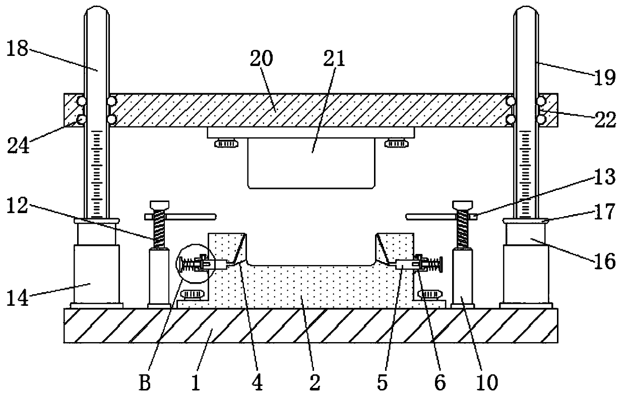
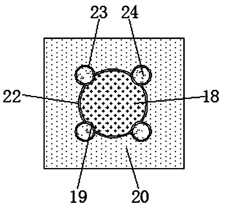
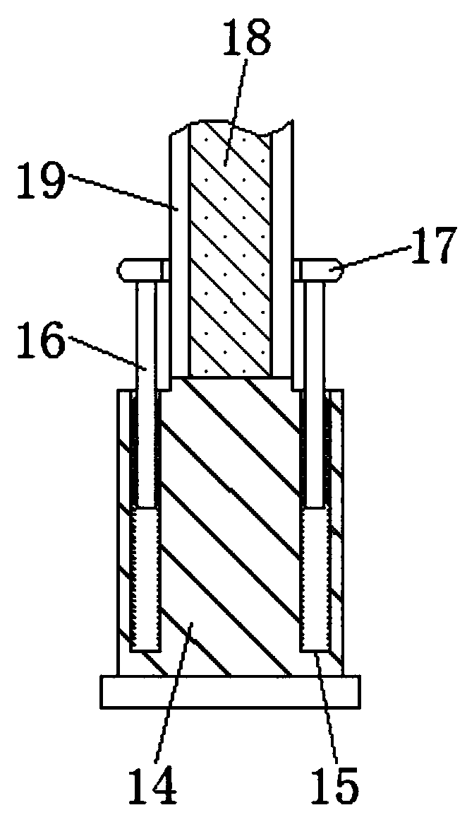
[0030] see Figure 1-8 , the present invention provides a technical solution: a forging punch die for reducing workpiece wear, including a worktable 1, a mounting rod 10, a fixing seat 14 and a mounting plate 20, and a stamping lower die 2 is installed above the worktable 1 , and a line groove 3 is reserved on the stamping lower die 2, a discharge hole 4 and a storage cavity 5 are respectively reserved inside the stamping lower die 2, and the discharge hole 4 ...


PUM


Abstract

The invention discloses a forging punch die facilitating workpiece abrasion reduction. A workbench plate, installing rods, fixing bases and an installing plate are included. A lower punching die bodyis arranged above the workbench plate. A wire groove is reserved in the lower punching die body. A discharging hole and a storage cavity are reserved in the lower punching die body and are connected.The installing plate is located above the lower punching die body, penetrating holes are reserved in the installing plate, grooves are formed in the outer sides of the penetrating holes, and balls arearranged on the inner sides of the grooves and located on the inner sides of guiding grooves. The installing plate is connected with guide rods through the penetrating holes and the balls. Accordingto the forging punch die facilitating workpiece abrasion reduction, the punching gap between an upper punching die body and the lower punching die body can be adjusted, so that the problems that a workpiece is excessively punched and the workpiece cannot be normally taken out of the die are solved; and meanwhile the situation that since workpiece punching is not conducted in place, normal usage cannot be achieved is prevented.

Description

technical field [0001] The invention relates to the technical field of stamping, in particular to a forging punch die which is convenient for reducing workpiece wear. Background technique [0002] Stamping and forging is a processing method of metal parts in the industrial field. Usually, the upper die and the lower die are used to cooperate to stamp out the plate-shaped metal material into a specified shape, which is convenient for subsequent processing and use. However, the stamping process of workpiece parts is currently Excessive wear of the workpiece usually occurs during the stamping process, which leads to inaccurate stamping dimensions of the workpiece, resulting in substandard processing quality, which is not conducive to subsequent use, and the serious wear of the workpiece during the stamping process is mainly due to the following two reasons: [0003] 1. It is inconvenient to control and adjust the punching gap of the existing punching die. Excessive punching of ...

Claims


Application Information

Patent Timeline
Patent Type & Authority Applications(China)
IPC IPC(8): B21D37/10B21D37/12B21D37/16
Inventor 不公告发明人
Owner WANGCHENG COUNTY WUSHAN LIANXIANG HEAVY FORGING CO LTD
Learn More