Efficient sand mixer

A sand mixer and sand mixing technology, which is applied in the cleaning/processing machinery of casting mold materials, casting molding equipment, metal processing equipment, etc., can solve the problems affecting the quality of molding sand, cleaning troubles, sand mixer damage, etc., to achieve The effect of shortening the mixing time, saving molding sand resources and improving sand mixing efficiency

Pending Publication Date: 2019-05-10
杭州海伦铸钢有限公司
View PDF0 Cites 6 Cited by
  • Summary
  • Abstract
  • Description
  • Claims
  • Application Information

AI Technical Summary

Problems solved by technology

[0002] As equipment for mixing molding sand, sand mixers are widely used in the foundry industry. During the sand mixing process of traditional sand mixers, the molding sand often sticks to the inner wall of the sand mixer shell, resulting in sand mixing. If it is not uniform, it cannot ensure that the molding sand mixing meets the required standards, which will affect the quality of the molding sand and cannot meet the needs of foundry production. When the molding sand is hardened, it may not be possible to completely unload the mixed molding sand, and it will stick to the sand mixer shell for a long time. After the molding sand is hardened, it will become very troublesome to remove it from the sand mixer shell. When the sand is mixed for the first time, hard particles will be produced in the molding sand, which cannot meet the requirements of use, which also causes a waste of molding sand resources. At the same time, some operators prevent the molding sand from sticking to the sand mixer shell by beating the sand mixer shell. , so it is easy to cause damage to the sand mixer and affect the service life of the sand mixer. In the existing sand mixer, during the molding sand mixing process, the mixing degree of materials is difficult to achieve the desired effect. The mixing time of the sand mixer is long, Unstable, low efficiency of molding sand mixing

Method used


Image

  • Efficient sand mixer
  • Efficient sand mixer
  • Efficient sand mixer

Examples


Embodiment Construction

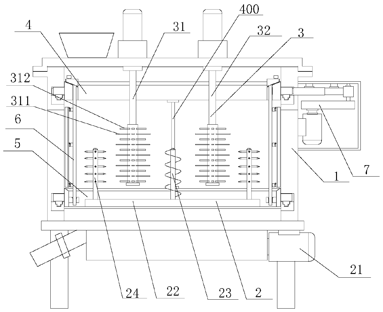
[0021] refer to Figure 1 to Figure 7 An efficient sand mixer of the present invention comprises a sand mixing cylinder 1, a chassis sand mixing mechanism 2, an eccentric stirring mechanism 3, an upper plate driven by a dial 4, a lower plate supported by a dial 5, a scraper dial assembly 6 and an upper plate A driving mechanism 7, a chassis sand mixing mechanism 2 is installed on the bottom of the sand mixing cylinder 1, and several auxiliary stirring mechanisms are arranged on the chassis sand mixing mechanism 2, and the auxiliary stirring mechanisms include a central mixing mechanism installed on the swivel seat 22 Spiral stirring shaft 23, two outer stirring shafts 24 and the first driving motor 21 that drives the rotation of the turntable 22, the central spiral stirring shaft 23 is installed at the center of the turntable 22, and the outer stirring shafts 24 are symmetrically distributed in the center On both sides of the spiral stirring shaft 23, several stirring rods are...


PUM


Abstract

The invention provides an efficient sand mixer. The efficient sand mixer comprises a sand mixing cylinder, a base plate sand mixing mechanism, an eccentric stirring mechanism, a shifting plate drivingupper disc, a shifting plate supporting lower disc, material scraping shifting plate assemblies and an upper disc driving mechanism, wherein the bottom of the sand mixing cylinder is provided with the base plate sand mixing mechanism, an auxiliary stirring mechanism is arranged on the base plate sand mixing mechanism, the eccentric stirring mechanism comprises a first stirring mechanism and a second stirring mechanism, the upper disc driving mechanism controls the shifting plate driving upper disc to rotate through a gear driving mechanism, the plurality of material scraping shifting plate assemblies are distributed in the sand mixing cylinder at intervals in the circumferential direction, the upper ends and the lower ends of the material scraping shifting plate assemblies are arranged onthe shifting plate driving upper disc and the shifting plate supporting lower disc respectively, and scraping plates which are matched with the inner wall of the sand mixing cylinder in an abutting mode are arranged on the material scraping shifting plate assemblies. Thus, the mixing time can be shortened, the sand mixing efficiency is improved, molding sand sticking to the inner wall of a shellof the sand mixer can be timely removed, and uniform sand mixing is ensured.

Description

【Technical field】 [0001] The invention relates to the technical field of sand mixers, in particular to an efficient sand mixer. 【Background technique】 [0002] As equipment for mixing molding sand, sand mixers are widely used in the foundry industry. During the sand mixing process of traditional sand mixers, the molding sand often sticks to the inner wall of the sand mixer shell, resulting in sand mixing. If it is not uniform, it cannot ensure that the molding sand mixing meets the required standards, which will affect the quality of the molding sand and cannot meet the needs of foundry production. When the molding sand is hardened, it may not be possible to completely unload the mixed molding sand, and it will stick to the sand mixer shell for a long time. After the molding sand is hardened, it will become very troublesome to remove it from the sand mixer shell. When the sand is mixed for the first time, hard particles will be produced in the molding sand, which cannot mee...

Claims


Application Information

Patent Timeline
Patent Type & Authority Applications(China)
IPC IPC(8): B22C5/04
Inventor 罗晓明裘国良关春健万兴国潘建华张清勤
Owner 杭州海伦铸钢有限公司
Why Eureka
Try Eureka