
Binding device for roll-dividing machine and binding method

A technology of a coiler and a rotating device, which is applied to the parts of the binding machine, can solve the problems of low binding efficiency and finger scratches, and achieve the effects of improving binding efficiency, reducing labor intensity, and avoiding scratches on binding wires

Pending Publication Date: 2019-05-10
山东鲁普耐特机械有限公司
View PDF6 Cites 2 Cited by
  • Summary
  • Abstract
  • Description
  • Claims
  • Application Information

AI Technical Summary

Problems solved by technology

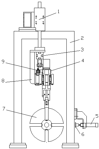
During the winding process, the small rolls need to be bound to prevent the wound rope from loosening. However, the current binding process is done manually, the binding efficiency is low, and it is easy to scratch the fingers.

Method used


Image

  • Binding device for roll-dividing machine and binding method
  • Binding device for roll-dividing machine and binding method
  • Binding device for roll-dividing machine and binding method

Examples


Embodiment Construction

[0025] In order to clearly illustrate the technical features of the solution, the solution will be described below through specific implementation modes.

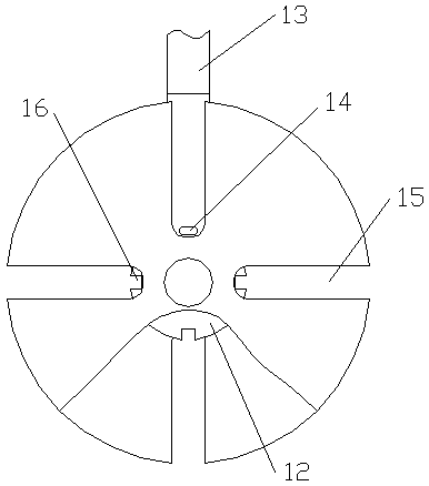
[0026] A rope reel for a winding machine, comprising a horizontally placed mandrel 12 driven by a driving motor and baffles 7 located at both ends of the mandrel, wherein one end of the baffle is fixedly connected to the mandrel, and the other end of the baffle is connected to the mandrel. Detachable connection, the detachable connection can be a key connection, or the baffle can be pressed on the end of the mandrel, as long as the two baffles and the mandrel rotate synchronously, after the winding is completed, the other end of the baffle and the The mandrel is split for easy removal of the coil. On the surface of the mandrel 12, there are several threading grooves 16 distributed in the circumferential direction and penetrating in the axial direction. Threading gap 15, after the small rope winding system is completed, the...


PUM


Abstract

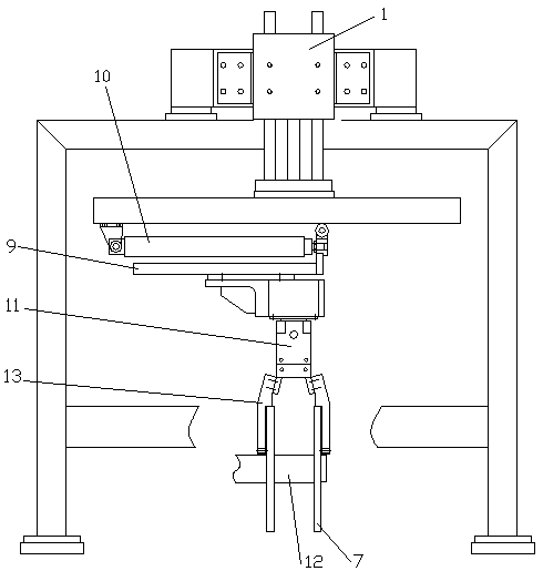
The invention relates to a binding device for a roll-dividing machine and a binding method. The binding device comprises a connecting frame,a binding machine rack and a binding lifting device, whereinthe binding machine rack is fixedly arranged, the binding lifting device is mounted on the binding machine rack and drives the connecting frame to move vertically, a rotary device and a finger air cylinder are mounted on the connecting frame, the finger air cylinder is driven to rotateby the rotary device, two clamping jaws of the finger air cylinder are respectively and fixedly connected with clamping plates, the two clamping plates are respectively provided with wire threading holes, and when the finger air cylinder is loosened, the space between the two clamping plates is matched with theaxial width of a rope coil. According to the binding device for the roll-dividing machine and the binding method, the clamping plates are driven to drop and rise through the binding lifting device, lifting of the two ends of binding wires is achieved, the two binding wire heads are tightly bound through the action of the finger air cylinder, the finger air cylinder is driven to rotate through therotary device, and intertwining of the two binding wireheadsis achieved, so that manual rope coil binding is replaced, the binding efficiency is greatly improved, the labor intensity of workers is reduced, and meanwhile scratching of workers by the binding wires in the binding process is avoided.

Description

technical field [0001] The invention relates to the field of rope decoiling equipment, in particular to a binding device and a binding method for a decoiling machine. Background technique [0002] In the production process of ropes, in order to improve the efficiency of rope collection, the finished ropes are usually wound into large rolls, and then divided into rolls according to sales or use requirements, and then the divided small rolls are packaged and transported. During the coiling process, the small rolls need to be bound to prevent the wound rope from loosening. However, the current binding process is done manually, which has low binding efficiency and is prone to scratching fingers. Contents of the invention [0003] Aiming at the above situation, the present invention provides a binding device and binding method for a coiler, which can replace the manual binding of rope rolls, which not only greatly improves the binding efficiency, but also prevents the staff fro...

Claims


Application Information

Patent Timeline
IPC IPC(8): B65B13/18
Inventor 巩玉动辛德洋
Owner 山东鲁普耐特机械有限公司
Learn More