
A wire harness winding device

A wire winding device and wire harness technology, applied in the field of wire harness processing, can solve the problems of complex structure of the device, lack of adaptability of the wire winding device, etc., and achieve the effect of high guiding precision

Active Publication Date: 2020-11-10
芜湖文青机械设备设计有限公司
View PDF9 Cites 0 Cited by
  • Summary
  • Abstract
  • Description
  • Claims
  • Application Information

AI Technical Summary

Problems solved by technology

[0004] The Chinese patent application publication number is CN206985356 discloses a winding machine, the winding device includes a support base, a first winding bracket, a first winding shaft, a second winding bracket, a second winding shaft, a transition bracket, a transition Board, infrared limiter and infrared signal receiver, adopting this technical scheme, the winding machine can ensure that the two winding shafts continue to work, and automatically turn to the second winding shaft to work after the winding of one winding shaft is completed, avoiding The occurrence of shutdown and unloading during the winding process greatly improves the efficiency of winding, but the structure of the whole device is too complicated, and at the same time, this technical solution is not suitable for the case where the wire harness to be wound is relatively short
[0005] After careful analysis of the above two comparison documents, it is found that the technical solutions involved in the comparison documents have their own problems, and the entire winding device lacks certain adaptability. design

Method used


Image

  • A wire harness winding device
  • A wire harness winding device
  • A wire harness winding device

Examples


Embodiment 1

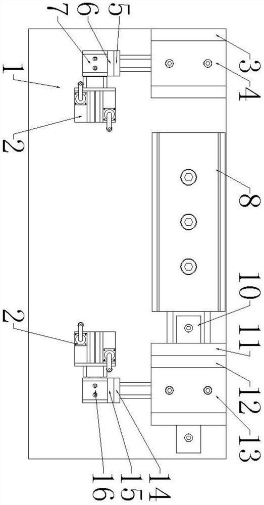
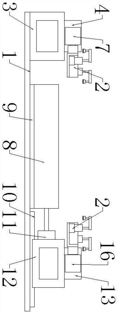
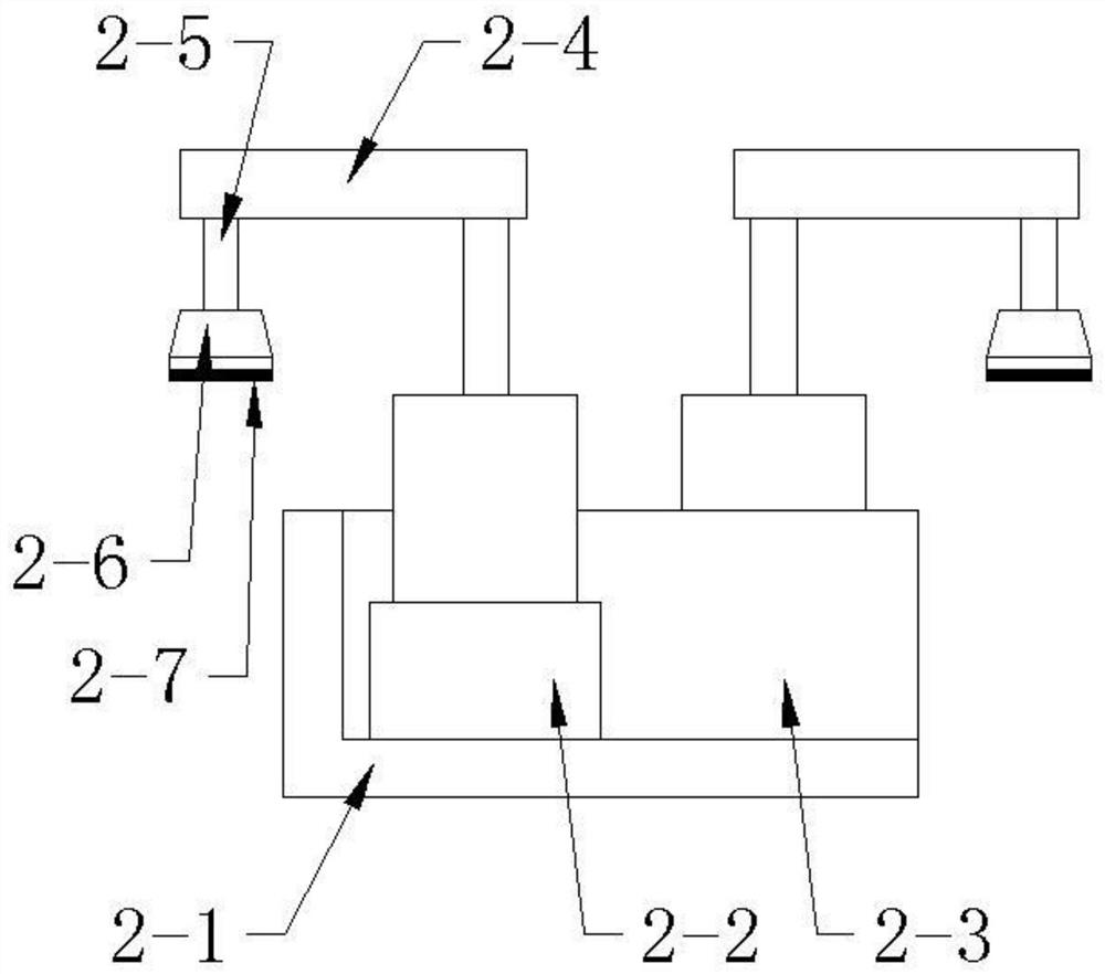
[0022] Such as Figure 1 to Figure 5 As shown, a wire harness winding device includes a bottom plate 1 and a winding mechanism 2 symmetrically installed on the left and right sides of the bottom plate 1. The winding mechanism 2 includes an L-shaped support plate 2-1 and a The V-shaped block 2-3 in the middle part of the plate 2-1, the two sides of the L-shaped support plate 2-1 are respectively equipped with corner cylinders 2-2, and the corner cylinders 2-2 on both sides are symmetrical about the center of the V-shaped block 2-3 , the output shaft of the corner cylinder 2-2 is fixedly installed with a mounting plate 2-4, the lower end of the mounting plate 2-4 is vertically equipped with a support column 2-5, and the lower end of the support column 2-5 is connected to There are pressing blocks 2-6, and a spacer 3 and a left displacement cylinder 4 are also installed on the left side of the base plate 1. The spacer 3 is fixedly installed on the base plate 1, and the left displ...

Embodiment 2

[0026] Such as Figure 1 to Figure 5As shown, a wire harness winding device includes a bottom plate 1 and a winding mechanism 2 symmetrically installed on the left and right sides of the bottom plate 1. The winding mechanism 2 includes an L-shaped support plate 2-1 and a The V-shaped block 2-3 in the middle part of the plate 2-1, the two sides of the L-shaped support plate 2-1 are respectively equipped with corner cylinders 2-2, and the corner cylinders 2-2 on both sides are symmetrical about the center of the V-shaped block 2-3 , the output shaft of the corner cylinder 2-2 is fixedly installed with a mounting plate 2-4, the lower end of the mounting plate 2-4 is vertically equipped with a support column 2-5, and the lower end of the support column 2-5 is connected to There are pressing blocks 2-6, and a spacer 3 and a left displacement cylinder 4 are also installed on the left side of the base plate 1. The spacer 3 is fixedly installed on the base plate 1, and the left displa...


PUM


Abstract

The invention discloses a wire winding device, and relates to the technical field of wire processing. The device comprises a bottom plate and winding mechanisms which are arranged on the left side andright side of the bottom plate; the left side of the bottom plate also comprises a cushion block and a left displacement cylinder; the cushion block is fixedly arranged on the bottom plate; the leftdisplacement cylinder is arranged on the cushion block through screws; the winding mechanism on the left side is arranged at the end of the piston rod of the left displacement cylinder; the right sideof the bottom plate also comprises a base plate and a wire adjusting cylinder; the base plate is fixedly arranged on the bottom plate; the wire adjusting cylinder is arranged on the base plate through screws; the tail end of the piston rod of the wire adjusting cylinder is provided with a connecting block and is connected with a sliding block; the lower end of the sliding block is slidably connected with a guide rail; the guide rail is arranged on the bottom plate through screws; the upper end face of the sliding block is provided with a right displacement cylinder through screws; the windingmechanism on the right side is arranged at the end of the piston rod of the right displacement cylinder. According to the invention, by arranging the winding mechanisms on the left side and right side, the mutual wire winding action of the is achieved.

Description

technical field [0001] The invention relates to the technical field of wire harness processing, in particular to a wire harness winding device. Background technique [0002] The wiring harness is the wiring part that connects various electrical equipment in the circuit, and is composed of insulating sheaths, terminal blocks, wires and insulating wrapping materials. In the process of wire harness processing, it is often necessary to wind the processed wire harnesses together. At present, the winding of wire harnesses is mainly carried out manually without special winding tools, so the efficiency of winding wires is very low, and the labor of workers The strength is very high, the shape of the wire harness wound out is not uniform, time-consuming and laborious, and the wire harness wound out is not beautiful. [0003] The Chinese patent application publication number is CN203033543U discloses a wire harness winding device, including a winding roller and a tail size control ji...

Claims


Application Information

Patent Timeline
Patent Type & Authority Patents(China)
IPC IPC(8): B65H54/20B65H75/28
CPCB65H54/20B65H75/285
Inventor 朱磊马能发李华郑凯邱亮亮施其兵方良周前宽张冲张静冯瑞叶立新张建军杨开文
Owner 芜湖文青机械设备设计有限公司
Learn More