Regulating valve detection device

A detection device and control valve technology, applied in valve devices, engine components, mechanical equipment, etc., can solve the problem of failure analysis of control valves that cannot detect data transmission, maintenance of missing control valves, inability to achieve online, timely and effective control and analysis and adjustment Valve operation information and other issues, to achieve the effect of predictive maintenance, extensive application, efficient maintenance programs and on-site maintenance services

Active Publication Date: 2019-05-10
徐州化工机械有限公司
View PDF4 Cites 3 Cited by
  • Summary
  • Abstract
  • Description
  • Claims
  • Application Information

AI Technical Summary

Problems solved by technology

[0002] For the fault diagnosis of the regulating valve industry, most of them are realized by parking for maintenance, which will cause unnecessary maintenance or omit the regulating valve with hidden troubles
At present, the control valve fault diagnosis function modules are all based on intelligent valve positioners or actuators, so the control valve fault diagnosis device cannot be applied to control valves of various brands, specifications, and parameters.
[0003] At present, the on-site fault diagnosis device of the control valve cannot realize the targeted detection and analysis of the faulty control valve, and cannot transmit the detection data to the control valve manufacturing factory in time for timely fault analysis, and cannot realize online, timely, effective grasp and Analyze the operating information of the control valve

Method used


Image

  • Regulating valve detection device
  • Regulating valve detection device
  • Regulating valve detection device

Examples


Embodiment 1

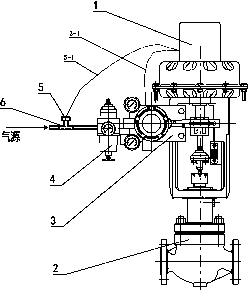
[0025] Such as figure 1 As shown, a regulating valve detection device, the regulating valve 2 is connected with an actuator, and a positioner 3 is installed on the actuator; One end of the tee 6 is connected to the air source pressure sensor 5 . An input signal collector for monitoring the input signal of the positioner 3 is installed in the positioner 3 .

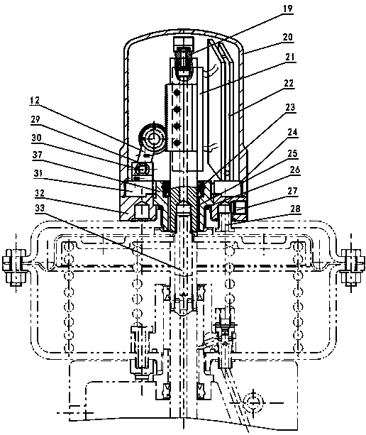
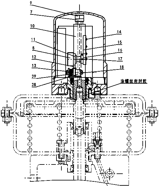
[0026] recombine Figure 2 to Figure 5 as shown,

[0027] The connecting rod 10 is connected with the control rod of the actuator through the push rod 33 . The push rod 33 is a stepped shaft, and the two ends of the push rod 33 are threaded. One end of the push rod 33 is threaded to the control rod of the actuator, and the other end is threaded to the connecting rod 10. Has thread sealant. The push rod 33 , the control rod of the actuator, and the connecting rod 10 are through-holes, and the through-hole at the outer end of the connecting rod 10 is connected to the membrane chamber pressure sensor 7 and the dynamic th...

Embodiment 2

[0040] On the basis of above-mentioned embodiment one;

[0041] combine Figure 6 As shown, the circuit board system includes a fault diagnosis device and a detection data analysis software. The microprocessor of the fault diagnosis device is STM32F407, and the peripherals mainly include ADC, PWM, WIFI, USB, RS232 and touch screen. The touch screen is the above-mentioned embodiment 1. LCD screen 36.

[0042] When fault diagnosis is to be performed on the valve, the operator sends a diagnosis instruction to the regulating valve diagnosis system through the touch screen. After receiving the instruction, the microprocessor generates PWM to output 4-20mA current. After the positioner receives the current signal, it controls the opening and closing of the valve. At this time, the membrane chamber pressure sensor 7, the dynamic thrust strain sensor 9, the displacement sensor 8, and the air source pressure sensor 5 collect valve data, and transmit the data to the STM32F407 micropr...


PUM


Abstract

The invention discloses a regulating valve detection device. A regulating valve is connected with an execution mechanism. A positioner is mounted on a regulating valve. The outer end of a control lever of the execution mechanism is connected with a connecting rod. The axis of the connecting rod is provided with a through hole. The outer end of the connecting rod is connected with a membrane chamber pressure sensor and a dynamic thrust strain sensor through a straight joint. A displacement sensor is further mounted on the connecting rod. An air inlet pipe of the execution mechanism is connectedwith an air source pressure sensor. The positioner is internally provided with an input signal collector used for monitoring input signals of the positioner. The regulating valve detection device canmonitor the actual operation conditions of the regulating valve, control variation of technological parameters of a pipeline controlled through the regulating valve and realize predictive maintenanceon the regulating valve. The regulating valve detection device is provided with the multiple sensors, can be configured with various types of execution mechanisms and regulating valves and is extensive in application and capable of effectively realizing fault analysis, maintenance plan making and field maintenance service, and users can feel relieved to use.

Description

technical field [0001] The invention relates to the technical field of characteristic parameter detection of regulating valves, in particular to a regulating valve detection device. Background technique [0002] For the fault diagnosis of the regulating valve industry, most of them are realized by parking for maintenance, which will cause unnecessary maintenance or omit the regulating valve with hidden troubles. At present, the control valve fault diagnosis function modules are all based on intelligent valve positioners or actuators, so the control valve fault diagnosis device cannot be applied to control valves of various brands, specifications, and parameters. [0003] At present, the on-site fault diagnosis device of the control valve cannot realize the targeted detection and analysis of the faulty control valve, and cannot transmit the detection data to the control valve manufacturing factory in time for timely fault analysis, and cannot realize online, timely, effective...

Claims


Application Information

Patent Timeline
Patent Type & Authority Applications(China)
IPC IPC(8): F16K37/00
Inventor 程路
Owner 徐州化工机械有限公司
Why Eureka
Try Eureka