Injection molded cable joint

A cable joint and injection molding technology, which is applied in the direction of connection, contact parts, two-part connection device, etc., can solve the problems of blocking the conductive sleeve, non-conduction of the joint, complex structure of the conductive sleeve, etc., and achieves convenient production and simple structure. Effect

Pending Publication Date: 2019-05-10
ADVANCED PLATINUM TECH
View PDF0 Cites 2 Cited by
  • Summary
  • Abstract
  • Description
  • Claims
  • Application Information

AI Technical Summary

Problems solved by technology

[0002] The electrical connection between the cables is realized through the joints. The general joints include male joints and female joints. The male joints and the female joints are respectively provided with conductive needles and conductive sleeves. The conductive needles are inserted into the conductive sleeves to achieve conductive connection. The traditional In the production of joints, due to the complex structure of the conductive sleeve, if it is directly injected, the injection material will easily enter the conductive sleeve and block the conductive sleeve, which will easily cause the joint to be disconnected

Method used


Image

  • Injection molded cable joint
  • Injection molded cable joint
  • Injection molded cable joint

Examples


Embodiment 1

[0022] The specific implementation of this embodiment will be described below in conjunction with the accompanying drawings.

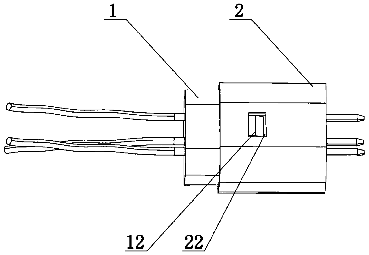
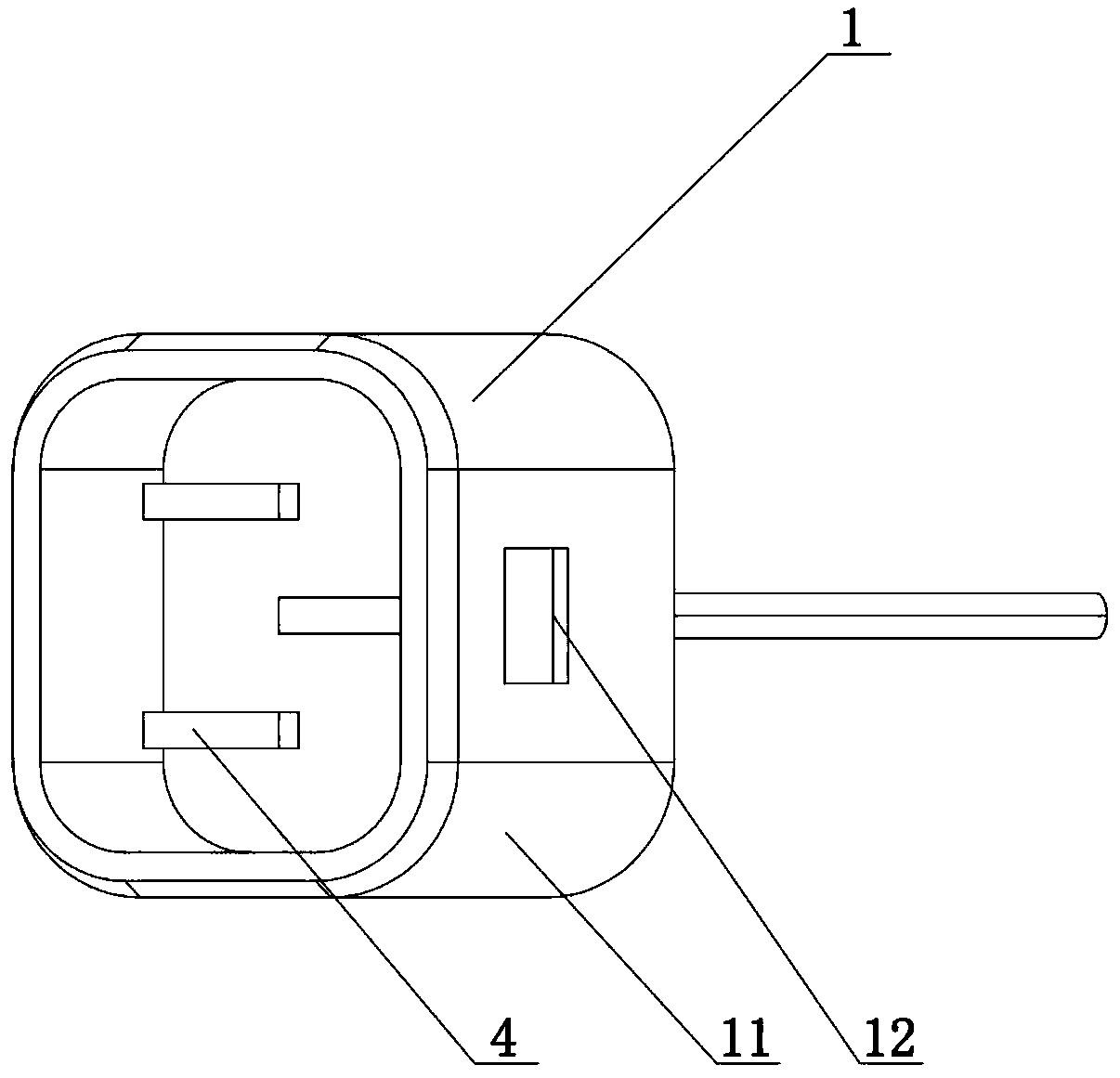
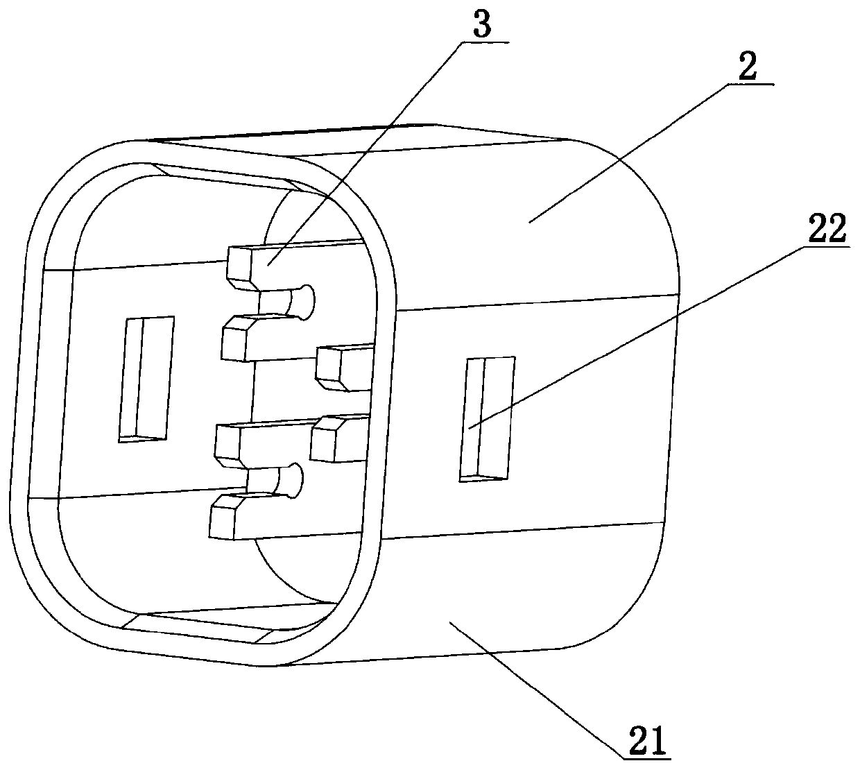
[0023] Such as Figure 1 to Figure 5 As shown, the injection molded cable connector of this embodiment includes a male connector 1 and a female connector 2, the male connector 1 includes three male connector conductive pieces, the male connector conductive piece is a conductive plug-in plate 4, and the outer side of the conductive plug-in plate 4 is injection-molded to connect the male connector. Joint injection molding shell 11, female joint 2 includes three female joint conductive pieces, female joint conductive piece is conductive fork 3, the outer side of conductive fork 3 is injection-molded to connect female joint injection-molded shell 21, male joint injection-molded shell 11 is provided with buckle 12, matched female joint The injection molded shell 21 of the connector is provided with a card slot 22, the injection molded shell 11 of the male c...

Embodiment 2

[0026] The specific implementation of this embodiment will be described below in conjunction with the accompanying drawings.

[0027] Such as Figure 1 to Figure 5 As shown, the conductive piece of the male connector in the male connector 1 of the injection molded cable connector of this embodiment is also a conductive fork 3, and the conductive fork 3 of the male connector 1 and the female connector 2 is vertically arranged, and the connecting groove 31 of the conductive fork 3 Relative to plug-in, the width of the connection groove 31 is slightly smaller than the thickness of the conductive fork 3 to ensure that the two conductive forks 3 are in close contact, and also ensure that the two conductive forks 3 are connected, thereby ensuring the connection between the male connector 1 and the female connector 2 .

[0028] When the injection molded cable connector is used, the male connector 1 and the female connector 2 are relatively plugged in, and the male connector 1 and the...


PUM


Abstract

The invention relates to an injection molded cable joint. The cable joint comprises a male joint and a female joint; the male joint comprises a plurality of male joint conductive sheets; the outer sides of the male joint conductive sheets are in injection molding connection with male joint injection molded shells; the female joint comprises a plurality of female joint conductive sheets; the outersides of the female joint conductive sheets are in injection molding connection with female joint injection molded shells; the male joint and the female joint are in matched connection through the male joint injection molded shells and the female joint injection molded shells; one ends of the male joint conductive sheets and the female joint conductive sheets are in contact connection when the male joint and the female joint are in assembly connection; and the other ends of the male joint conductive sheets and the female joint conductive sheets are connected with a cable. The injection moldedcable joint is simple in structure; injection molding production can be directly carried out, so that the production is convenient; and the connection between the male joint and the female joint can be ensured.

Description

technical field [0001] The invention relates to a cable joint, in particular to an injection molded cable joint. Background technique [0002] The electrical connection between the cables is realized through the joints. The general joints include male joints and female joints. The male joints and the female joints are respectively provided with conductive needles and conductive sleeves. The conductive needles are inserted into the conductive sleeves to achieve conductive connection. The traditional For joint production, due to the complex structure of the conductive sleeve, if it is directly injected, the injection molding material will easily enter the conductive sleeve and block the conductive sleeve, which will easily cause the joint to be disconnected. Contents of the invention [0003] In view of the above shortcomings, the applicant has conducted research and improvement, and provides an injection molded cable joint. [0004] The technical scheme adopted in the pres...

Claims


Application Information

Patent Timeline
Patent Type & Authority Applications(China)
IPC IPC(8): H01R13/04H01R13/11H01R13/405H01R13/46H01R13/627H01R13/631H01R24/00H01R24/20H01R24/28
Inventor 周敬训谷庆伟李晴
Owner ADVANCED PLATINUM TECH
Why Eureka
Try Eureka