Film scrap removal structure

A film and debris technology, applied in the field of film debris removal structure, can solve problems such as film debris flying around

Pending Publication Date: 2019-05-14
深圳市欧亚建设工程有限公司
View PDF0 Cites 0 Cited by
  • Summary
  • Abstract
  • Description
  • Claims
  • Application Information

AI Technical Summary

Problems solved by technology

[0005] An object of the present invention is to provide a structure for removing film debris, which can solve the problem of partially fragmented film fragments flying around in the film rolling process of the existing film stripping machine, and can make the fragmented fil

Method used


Image

  • Film scrap removal structure
  • Film scrap removal structure
  • Film scrap removal structure

Examples


Embodiment Construction

[0034] In order to further understand the present invention, preferred embodiments are listed below, together with the accompanying drawings and reference numerals, the specific components of the present invention and the effects achieved are described in detail as follows.

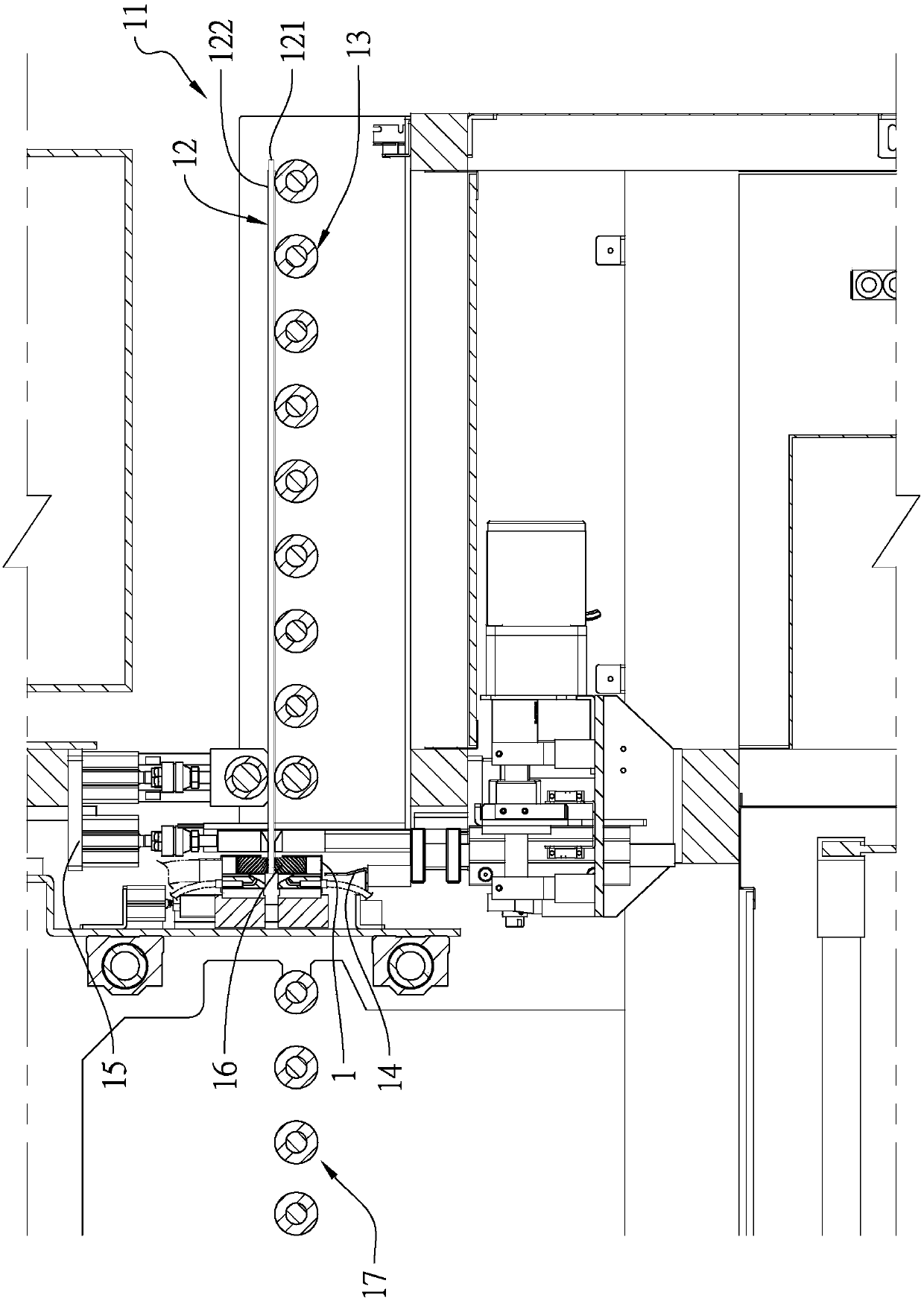
[0035] see figure 1 As shown, the film debris removal structure 1 of the present invention is used to remove the thin plate 12 film 122 debris on the film stripping machine 11, the thin plate 12 is a plate body such as a printed circuit board, at least one film 122 is combined with at least one substrate 121 on the photoresist layer on the side. During implementation, one end of the film stripping machine 11 input sheet 12 is defined as the front end of the film stripping machine 11 and the rear end of the sheet 12, and one end of the output sheet 12 is defined as the rear end of the film stripping machine 11 and the front end of the sheet 12, and the film stripping machine The front end of 11 has a fron...


PUM


Abstract

A film scrap removal structure is used for removing film scraps generated after a sheet on a stripping machine is rolled through a knurling wheel group. The knurling wheel group comprises upper and lower seats in vertical opposite arrangement, and an upper knurling wheel group and a lower knurling wheel group are arranged on one sides of front ends of the upper and lower seats and synchronously and horizontally move to roll front end edges of films on upper and lower surfaces of the sheet. An upper cover is fixed to the upper seat to cover the upper knurling wheel group, a lower cover is fixedto a lower seat to cover the lower knurling wheel group, and in operating of an air suction device, the film scraps can be driven to move outwards through an air suction hole in the top end of the upper cover.

Description

technical field [0001] The invention relates to a structure for removing film debris, in particular to a structure which can effectively remove partially broken film debris during the film rolling process of a film stripping machine. Background technique [0002] In the manufacturing process of printed circuit boards, before the substrate is exposed, a photoresist layer and a film adhered to the surface of the photoresist layer are formed on the upper and lower surfaces of the substrate, and after exposure, the film is peeled off to make the photoresist layer exposed for subsequent developing and etching procedures. And the mode of peeling film of existing film stripping machine, mainly is to convey the above-mentioned thin plate such as printed circuit board through a front conveying section, make along the conveying direction from front to back, and the thin plate passes through the blocking positioning of a blocking unit, After rolling on the surface of the film by a set...

Claims


Application Information

Patent Timeline
IPC IPC(8): B32B38/10B32B38/16
Inventor 高亚松
Owner 深圳市欧亚建设工程有限公司
Why Eureka
Try Eureka