3D printing metal powder material manufacturing equipment

A technology of metal powder and 3D printing, which is applied in the field of 3D printing, can solve the problems that metal powder is easy to block in the screening hole and the screening hole is blocked, so as to solve the problem of flying around, better use effect and smooth flow sexual effect

Inactive Publication Date: 2021-06-04
JIANGSU VILORY ADVANCED MATERIALS TECH CO LTD
View PDF7 Cites 0 Cited by
  • Summary
  • Abstract
  • Description
  • Claims
  • Application Information

AI Technical Summary

Problems solved by technology

[0003] At present, the metal powder used in 3D printing needs to remove the larger particle impurities in the production process to ensure the stability of the metal powder during use. The removal process is mainly carried out by sieving, but due to There is relative friction between the metal powders, which makes the metal powders easily blocked in the sieve holes, and larger particle impurities will also block the sieve holes. Therefore, it is urgent to design a 3D printing metal powder Material manufacturing equipment to solve the above problems

Method used


Image

  • 3D printing metal powder material manufacturing equipment
  • 3D printing metal powder material manufacturing equipment
  • 3D printing metal powder material manufacturing equipment

Examples


Embodiment 1

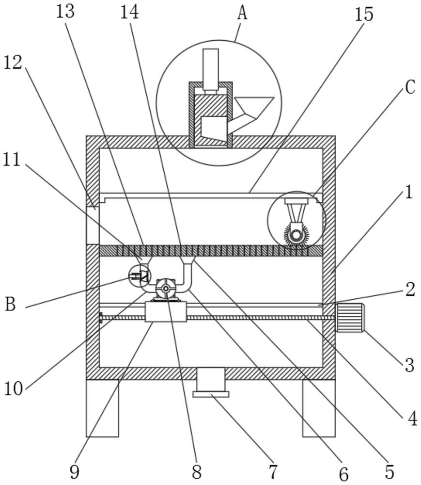
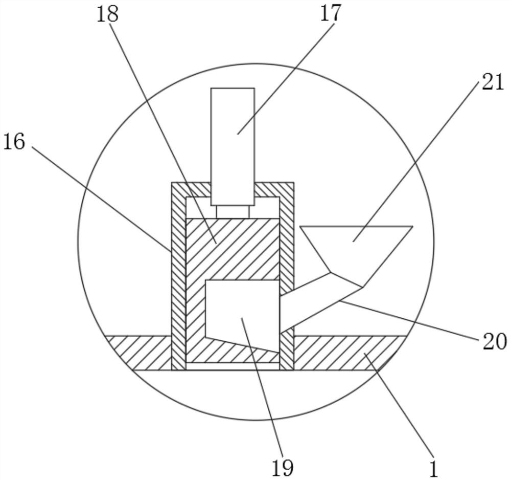
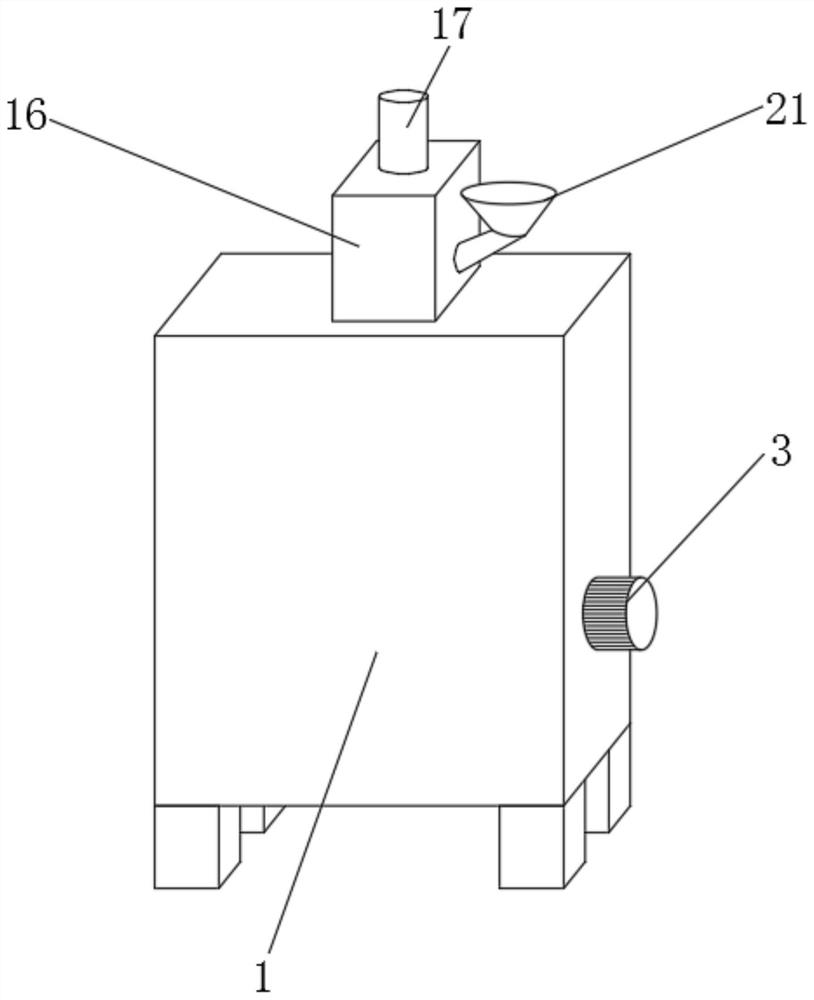
[0031] refer to Figure 1-5 , a 3D printing metal powder material manufacturing equipment, including a processing box 1, the top outer wall of the processing box 1 is provided with a feeding mechanism, the inner wall of the processing box 1 is provided with a sieve plate 13, and the top outer wall of the sieve plate 13 is provided with a plurality of Screening holes 14, a first motor 3 is arranged on one side outer wall of the processing box 1, and one end of the output shaft of the first motor 3 is provided with a screw rod 4, the outer wall thread of the screw rod 4 is provided with a movable block 9, and the inner wall of the processing box 1 is provided with There is a fixed rod 2, and the movable block 9 is slidably arranged on the fixed rod 2. The top outer wall of the movable block 9 is fixedly connected with a fan 8, and the exhaust end of the fan 8 is connected with an exhaust hood 11 through an exhaust pipe 10, and the air guide of the fan 8 End is connected with win...

Embodiment 2

[0040] refer to Figure 6 , a 3D printing metal powder material manufacturing equipment. Compared with Embodiment 1, this embodiment also includes that the inner walls on both sides of the processing box 1 are fixedly connected with material blocking plates 33 .

[0041] Working principle: when in use, the material blocking plate 33 can prevent metal powders from accumulating in the dead corners around the processing box 1 and cause difficulty in discharge, and the use effect is better.


PUM


Abstract

The invention discloses 3D printing metal powder material manufacturing equipment. The equipment comprises a treatment box, wherein a feeding mechanism is arranged on the outer wall of the top of the treatment box, a screen plate is arranged on the inner wall of the treatment box, a plurality of screening holes are formed in the outer wall of the top of the screen plate, a first motor is arranged on the outer wall of one side of the treatment box, a screw rod is arranged at one end of an output shaft of the first motor, a movable block is arranged on the outer wall of the screw rod in a threaded mode, a fixed rod is arranged on the inner wall of the treatment box, the movable block is slidably arranged on the fixed rod, a fan is fixedly connected to the outer wall of the top of the movable block, a draught hood is connected to the draught end of the fan through a draught pipe, an air guide end of the fan is connected to an air guide cover through an air guide pipe, and a discharging mechanism is arranged on the draught pipe. According to the equipment, the problem that metal powder flies everywhere can be well solved through intermittent feeding, the effect of well unblocking screening holes is achieved, the screening smoothness is effectively guaranteed, and the using effect is better.

Description

technical field [0001] The invention relates to the technical field of 3D printing, in particular to a 3D printing metal powder material manufacturing equipment. Background technique [0002] 3D printing is a technology based on digital model files, using bondable materials such as powdered metal or plastic, to construct objects by layer-by-layer printing. 3D printing is often used in mold manufacturing, industrial design and other fields. The manufacturing model is gradually used in the direct manufacturing of some products, which has a profound impact on the traditional process flow, production line, factory model, and industrial chain combination. It is a representative disruptive technology in the manufacturing industry. [0003] At present, the metal powder used in 3D printing needs to remove the larger particle impurities in the production process to ensure the stability of the metal powder during use. The removal process is mainly carried out by sieving, but due to T...

Claims


Application Information

Patent Timeline
Patent Type & Authority Applications(China)
IPC IPC(8): B22F1/00B22F12/00B33Y40/10
CPCB33Y40/10B22F1/14
Inventor 许荣玉蒋保林叶国晨张柯唐跃跃魏放蒋陈张波王浩州张凯
Owner JIANGSU VILORY ADVANCED MATERIALS TECH CO LTD
Why Eureka
Try Eureka