In-furnace stabilizing roller regulating device

A technology of adjusting device and stabilizing roller, which is applied in the direction of coating, metal material coating process, hot-dip plating process, etc., and can solve problems such as jamming, product quality accidents, and easy scratching of strip steel

Active Publication Date: 2019-05-14
武汉钢铁有限公司
View PDF6 Cites 0 Cited by
  • Summary
  • Abstract
  • Description
  • Claims
  • Application Information

AI Technical Summary

Problems solved by technology

[0002] In the hot-dip galvanizing production process, the vibration of the strip steel in the furnace nose has a direct impact on the surface quality of the product. Therefore, many high-quality hot-dip galvanizing production lines will install Stabilizing rolls, under the influence of high temperature environment in the furnace, the stabilizing rolls will be deformed and jammed, and nodules and other sundries on the roll surface will easily scratch the strip steel, resulting in product quality accidents
[0003] At present, due to the limited space in the furnace nose, most of the stabilizing rollers adopt a fixed structure. Although the installation is simple, once damaged, a large number of strip steel scratches will occur, requiring emergency shutdown for repairs, which brings hidden dangers to normal production

Method used


Image

  • In-furnace stabilizing roller regulating device
  • In-furnace stabilizing roller regulating device
  • In-furnace stabilizing roller regulating device

Examples


Embodiment Construction

[0021] The present invention will be further described below in conjunction with the accompanying drawings and embodiments.

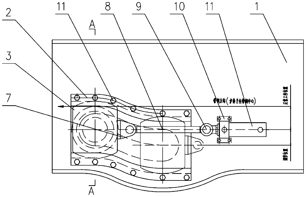
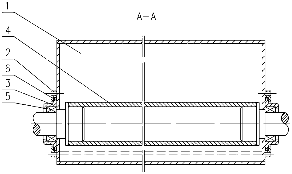
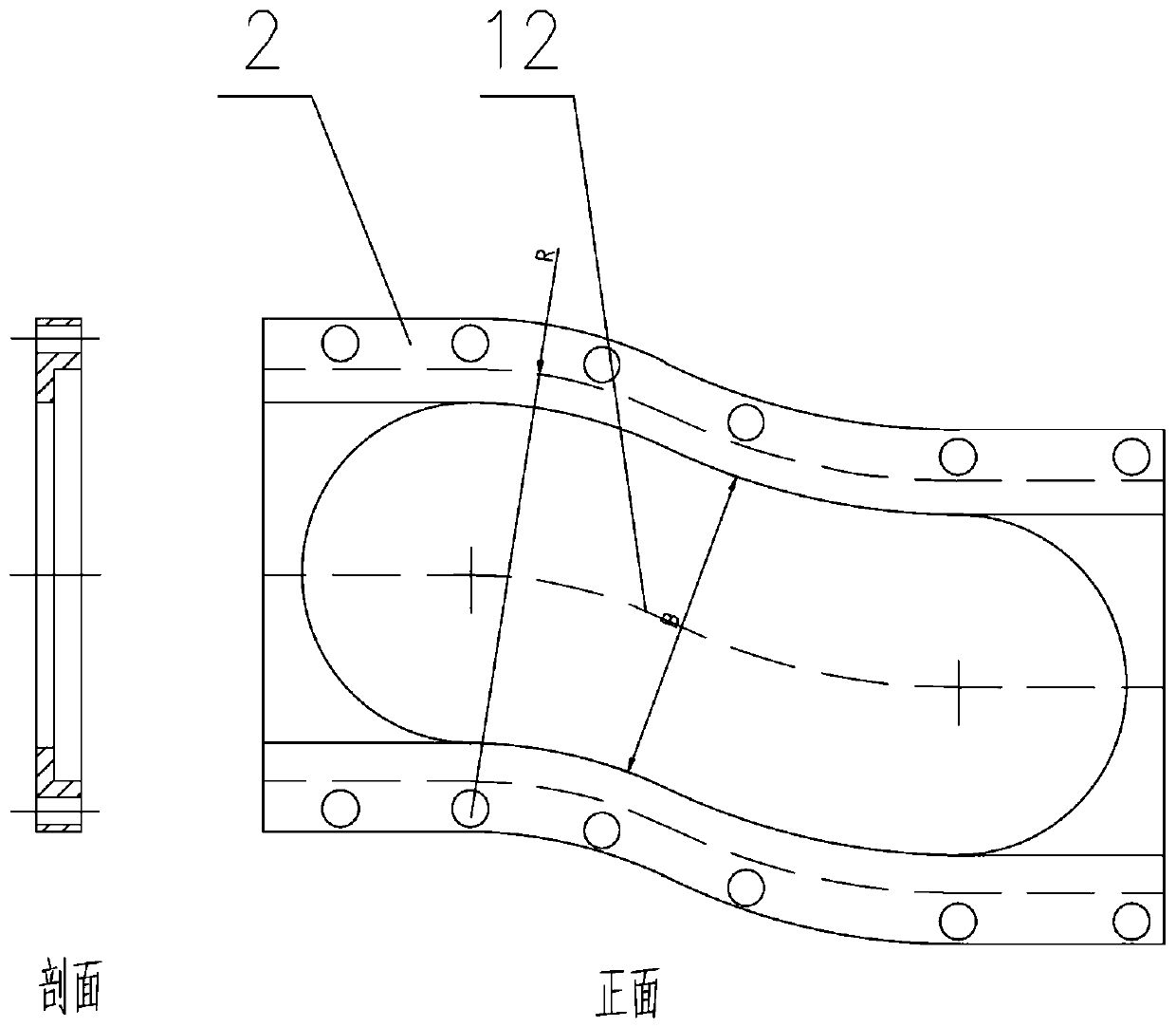
[0022] Such as Figure 1 to Figure 4 As shown, a stabilizing roller adjustment device in a furnace includes a furnace nose 1 with a streamlined concave area at the bottom, arc-shaped groove rails 2 symmetrically arranged on both sides of the furnace nose 1, and installed on the furnace through bearing seats 3 on both ends. The stabilizing roller 4 in the arc-shaped groove rail 2 on both sides, the push rod mechanism that can drive the stabilizing roller 4 to move along the arc-shaped groove rail 2 through the bearing seat 3, the top surface of the bearing seat 3 in contact with the groove inner wall of the arc-shaped groove rail 2 and the bottom surface are both arc surfaces 13 and the farthest distance between the two arc surfaces 13 is compatible with the gauge of the arc groove rail 2. When the bearing seat 3 moves to the high point of the arc groove...


PUM


Abstract

The invention discloses an in-furnace stabilizing roller regulating device. The in-furnace stabilizing roller regulating device comprises a furnace nose, arc-shaped groove rails, stabilizing rollers and a push rod mechanism, wherein the arc-shaped groove rails are symmetrically arranged at the two sides of the furnace nose; the stabilizing rollers are correspondingly installed inside the arc-shaped grooved rails arranged at the two sides by virtue of bearing seats; the push rod mechanism can be used for driving each stabilizing roller to move along the corresponding arc-shaped grooved rail byvirtue of the corresponding bearing seat; the top surface and the bottom surface, making contact with the inner wall of a groove of the corresponding arc-shaped grooved rail, of each bearing seat areeach a circular arc surface; the distance between the most remote ends of the two circular arc surfaces is adaptive to the distance between the arc-shaped grooved rails; when each bearing seat moves to a high-position point of the corresponding arc-shaped groove rail, the corresponding stabilizing roller can be tangential to tension band steel; and when each bearing seat moves to a low-position point of the corresponding arc-shaped groove rail, the corresponding stabilizing roller is positioned over a sunken region. The in-furnace stabilizing roller regulating device disclosed by the inventioncan be used for regulating the position of each stabilizing roller, realizes quick and smooth switching of the working state and the overhauling state of the stabilizing rollers and enlarges the installation space for the furnace nose.

Description

technical field [0001] The invention belongs to the field of metallurgy and steel rolling machinery, and in particular relates to a stabilizing roll adjusting device in a furnace. Background technique [0002] In the hot-dip galvanizing production process, the vibration of the strip steel in the furnace nose has a direct impact on the surface quality of the product. Therefore, many high-quality hot-dip galvanizing production lines will install Stabilizing rolls, under the influence of the high temperature environment in the furnace, the stabilizing rolls will be deformed and jammed, and nodules and other sundries on the roll surface will easily scratch the strip steel, resulting in product quality accidents. [0003] At present, due to the limited space in the furnace nose, most of the stabilizing rollers adopt a fixed structure. Although the installation is simple, once damaged, a large number of strip steel scratches will occur, requiring emergency shutdown for repairs, wh...

Claims


Application Information

Patent Timeline
Patent Type & Authority Applications(China)
IPC IPC(8): C23C2/06C23C2/40
Inventor 李良洪陈刚刘傲何明生王育林
Owner 武汉钢铁有限公司
Why Eureka
Try Eureka