
Vehicle jitter control method and device, drive control system and vehicle

A vehicle and drive motor technology, which is applied in the direction of control drive, control device, vehicle components, etc., can solve the problems affecting driving comfort, affecting the acceleration performance of the whole vehicle, and delaying the speed and phase of the drive motor, so as to achieve obvious start-up jitter and start-up jitter The effect of improving and removing the amount of interference

Active Publication Date: 2020-12-01
BEIJING CHJ AUTOMOTIVE TECH CO LTD
View PDF7 Cites 8 Cited by
  • Summary
  • Abstract
  • Description
  • Claims
  • Application Information

AI Technical Summary

Problems solved by technology

However, this method has obvious defects, mainly due to two reasons: first, increasing the torque command step size of the vehicle controller will affect the acceleration performance of the vehicle, resulting in poor driving experience
Second, the low-pass filter is used in the torque compensation link. The speed of the driving motor filtered by the low-pass filter has an obvious phase delay, resulting in a deviation in the amount of speed jitter obtained after passing the low-pass filter. This deviation cannot reflect the real The amount of speed jitter, and finally the compensation torque obtained after compensating the torque command according to the amount of speed jitter also has a phase delay
Therefore, the existing vehicle shake suppression effect is poor, affecting driving comfort

Method used


Image

  • Vehicle jitter control method and device, drive control system and vehicle
  • Vehicle jitter control method and device, drive control system and vehicle
  • Vehicle jitter control method and device, drive control system and vehicle

Examples


Embodiment Construction

[0027] Exemplary embodiments of the present disclosure will be described in more detail below with reference to the accompanying drawings. Although exemplary embodiments of the present disclosure are shown in the drawings, it should be understood that the present disclosure may be embodied in various forms and should not be limited by the embodiments set forth herein. Rather, these embodiments are provided for more thorough understanding of the present disclosure and to fully convey the scope of the present disclosure to those skilled in the art.

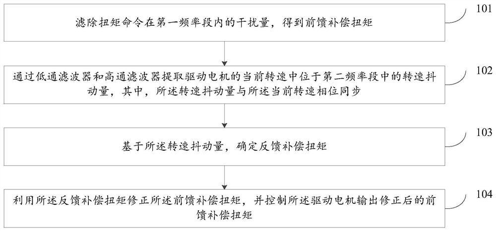
[0028] In the first aspect, the embodiments of the present disclosure provide a vehicle vibration control method, such as figure 1 As shown, the method mainly includes:

[0029] 101. Filter out the interference amount of the torque command in the first frequency band to obtain the feed-forward compensation torque.

[0030] In practical applications, the torque command can be generated under the following conditions during the use ...


PUM


Abstract

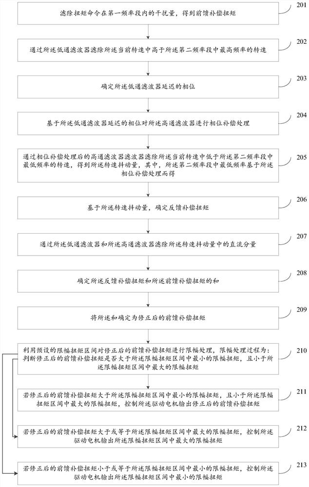
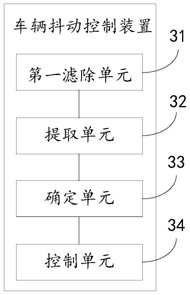
The embodiment of the disclosure discloses a vehicle jitter control method and device, a drive control system and a vehicle, relates to the technical field of vehicle control, and mainly aims to improve the effect of suppressing vehicle jitter. According to the main technical scheme, the method comprises the steps: filtering out the disturbance variable of a torque command in a first frequency band to obtain feedforward compensation torque; extracting a rotating speed jitter amount in a second frequency band in the current rotating speed of the driving motor through a low-pass filter and a high-pass filter, the rotating speed jitter amount being in phase synchronization with the current rotating speed; determining a feedback compensation torque based on the rotation speed jitter amount; and correcting the feedforward compensation torque by utilizing the feedback compensation torque, and controlling the driving motor to output the corrected feedforward compensation torque.

Description

technical field [0001] Embodiments of the present disclosure relate to the technical field of vehicle control, and in particular, to a vehicle shake control method and device, a drive control system, and a vehicle. Background technique [0002] As society has higher and higher requirements for environmental protection and energy conservation, new energy vehicles such as electric vehicles and hybrid vehicles have gradually become one of the main means of transportation for people to travel. New energy vehicles are usually driven by drive motors. When a new energy vehicle starts to accelerate or accelerates rapidly, a sudden change in the speed of the drive motor may cause the vehicle to vibrate, thereby reducing the user's driving experience. [0003] At present, in order to suppress the jitter of the vehicle, the usual method is to increase the step size of the torque command of the vehicle controller, and at the same time increase the torque compensation link to correct th...

Claims


Application Information

Patent Timeline
IPC IPC(8): B60L15/20
CPCB60L15/20B60L2240/421B60L2240/423Y02T10/72
Inventor 张龙刘涛
Owner BEIJING CHJ AUTOMOTIVE TECH CO LTD
Learn More