A method for measuring the relative radiation performance of large scanning angle sliding spotlight SAR satellite system

A relative radiation and sliding beamforming technology, applied in the field of remote sensing satellites, can solve the problems of uneven azimuth radiation, uneven range radiation, and difficulty in pattern measurement, and achieves reduced noise impact, high measurement accuracy and efficiency, The effect of improving image radiation quality

Active Publication Date: 2020-03-10
中国人民解放军61646部队
View PDF3 Cites 0 Cited by
  • Summary
  • Abstract
  • Description
  • Claims
  • Application Information

AI Technical Summary

Problems solved by technology

Compared with the traditional strip SAR, in addition to the inhomogeneous range radiation caused by the modulation of the range antenna pattern, the sliding spotlight SAR has the performance change of the azimuth antenna pattern in the azimuth scan, resulting in a unique azimuth antenna pattern. radiation inhomogeneity
Since there are many wave positions in the azimuth direction and the radar scans along the azimuth direction during the working process, the on-orbit measurement of the pattern is very difficult, and it is difficult to theoretically calculate and compensate the relative radiation performance based on the measurement results of the on-orbit pattern.

Method used


Image

  • A method for measuring the relative radiation performance of large scanning angle sliding spotlight SAR satellite system
  • A method for measuring the relative radiation performance of large scanning angle sliding spotlight SAR satellite system
  • A method for measuring the relative radiation performance of large scanning angle sliding spotlight SAR satellite system

Examples


Embodiment Construction
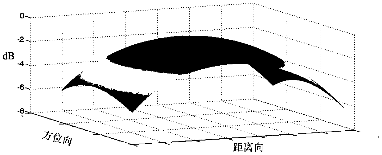
[0015] The basic idea of ​​the present invention is to use the uniform scattering scene as the observation area, on the basis of removing the non-uniform area, use the smoothing window to reduce the noise influence, and use the method of two-dimensional polynomial fitting to obtain the relative radiation characteristic measurement result of the system,

[0016] The present invention will be further described in detail with reference to the accompanying drawings and specific embodiments.

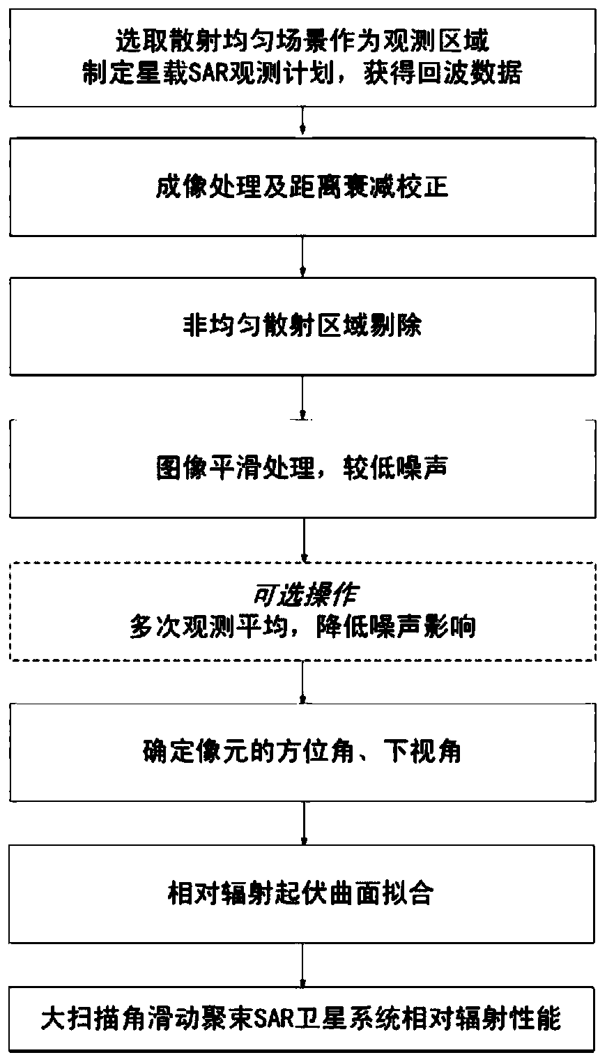
[0017] The present invention provides a method for measuring the relative radiation performance of a sliding spotlight SAR satellite system with a large scanning angle, the process is as follows figure 1 As shown, the method includes the following steps:

[0018] Step 1: Select the imaging area. After the SAR satellite and its ground data processing system have completed system performance tuning, the scene with uniform radar backscatter is selected as the imaging area.

[0019] In the spe...


PUM


Abstract

The invention discloses a method for measuring relative radiance of large-scanning angle sliding spotlight SAR satellite systems. The method comprises the steps of: selecting a uniform scattering scene as an imaging area; carrying out imaging and range attenuation correction on echo data to obtain single-looking complex image data; getting rid of non-uniform scattering area in the image so as to eliminate adverse effect of subsequent relative radiance measurement; smoothing the image by utilizing a certain rectangular window so as to reduce the noise influence and obtain an amplitude image; averaging multiple images with same beam positions to further reduce the noise influence; determining an azimuth angle and a lower visual angle corresponding to each pixel of the smoothed amplitude image according to radar parameters such as an azimuth scanning range, a range beam width and the like of radar; and carrying out even-order tow-dimensional surface polynomial fitting on the smoothed amplitude image by taking the azimuth angle and the lower visual angle as variables, so as to obtain relative radiance of a system. By utilizing the method, high-precision measurement results for relativeradiance of large-scanning angle sliding spotlight SAR satellite systems can be effectively obtained, so that the method can be used for relative radiation correction of the systems so as to improvethe image quality.

Description

technical field [0001] The invention belongs to the technical field of remote sensing satellites, in particular to the radiation correction technology of space-borne synthetic aperture radar. Background technique [0002] Synthetic Aperture Radar (SAR) satellite is an active remote sensing device that can work around the clock to obtain high-resolution SAR images of ground scenes. Sliding beamforming is a new working mode of synthetic aperture radar. By controlling the moving speed of the antenna azimuth beam on the ground, the azimuth coherent accumulation time is increased, thereby improving the azimuth resolution. Compared with the traditional strip SAR, in addition to the inhomogeneous range radiation caused by the modulation of the range antenna pattern, the sliding spotlight SAR has the performance change of the azimuth antenna pattern in the azimuth scan, resulting in a unique azimuth antenna pattern. Radiation inhomogeneity. Since there are many azimuth wave positi...

Claims


Application Information

Patent Timeline
Patent Type & Authority Patents(China)
IPC IPC(8): G01S7/40
Inventor 康利鸿孙希龙田菁黄建军郝继刚
Owner 中国人民解放军61646部队
Why Eureka
Try Eureka