Game controller and form conversion method and game operation mode switching method
A game controller and mode switching technology, applied in indoor games, video games, sports accessories, etc., can solve the problems of poor sense of game substitution, inconvenient operation, and difficulty in adapting to shooting game operation modes, so as to avoid joint stiffness and avoid Muscle soreness, the effect of improving the sense of game substitution
- Summary
- Abstract
- Description
- Claims
- Application Information
AI Technical Summary
Problems solved by technology
Method used
Image
Examples
Embodiment 1
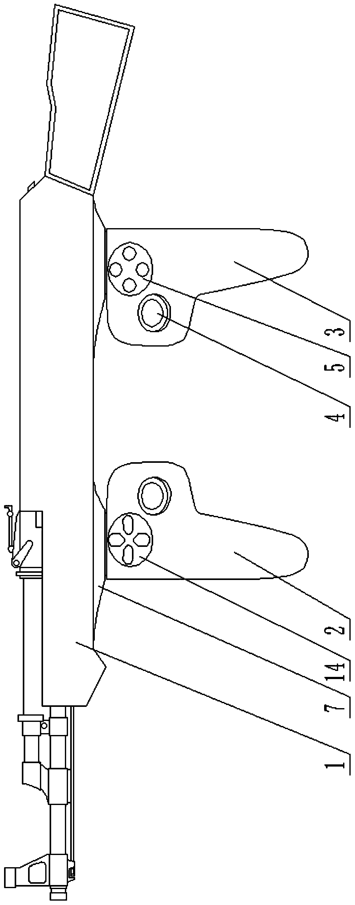
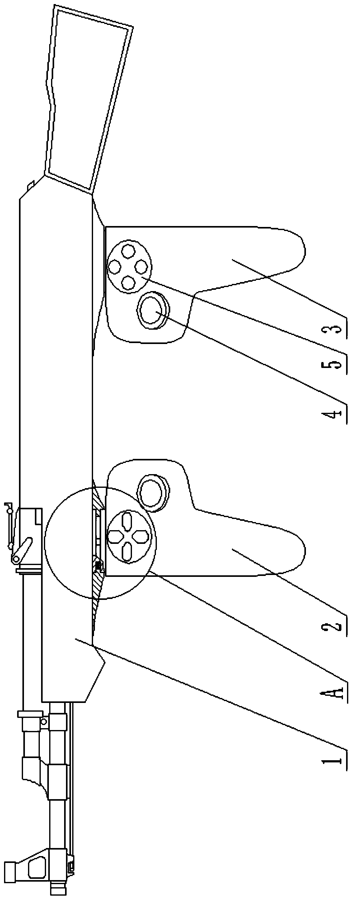
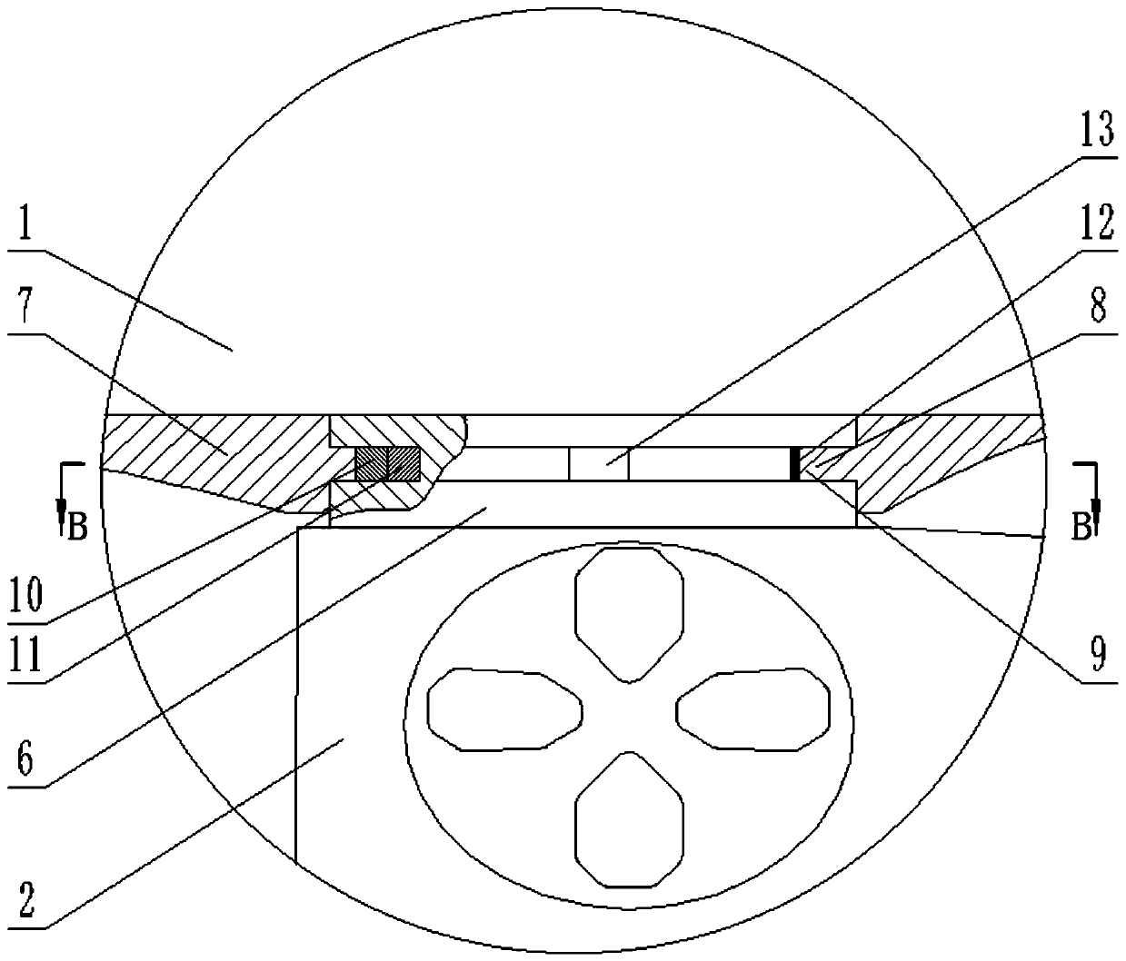
[0051] Such as Figure 1-Figure 2 A game controller shown includes a gun-shaped body 1, a mode switching mechanism, a screen positioning device and two handles. The gun-shaped body 1 is in the shape of a gun, and both handles are located at the lower part of the gun-shaped body 1. 2 and rear handle 3 ( figure 1 The muzzle of middle gun type body 1 is set to the left, and promptly the left end of gun type body 1 is the front end, and the right end of gun type body 1 is the rear end), and front handle 2 is positioned at the left side of rear handle 3. Both the front handle 2 and the rear handle 3 are provided with a game control device, and the game control device on the front handle 2 includes a direction control button 14 and a rocker 4 . Such as Figure 7-Figure 8 As shown, the game control device on the rear handle 3 includes a function control button 5 and a joystick 4 . The screen positioning device is a camera and an infrared light-transmitting sheet installed at the f...
Embodiment 2
[0061] Such as Figure 9 Shown, embodiment 2 is improved on the basis of embodiment 1. The handle of the gun-shaped body 1 in Embodiment 2 is in the shape of a cuboid, and its game operation mode is still the gun operation mode if it is set in this way, but the gun-shaped body 1 does not imitate the shape of a firearm, but it is easy to manufacture and low in cost.
[0062] The rest of the structure and working principle of embodiment 2 are the same as embodiment 1.
Embodiment 3
[0064] Embodiment 3 is improved on the basis of Embodiment 1. Specifically, in embodiment 3, an annular groove 8 is provided on the inner wall of the sleeve 7 along the circumferential direction, and a snap ring 9 snapped into the annular groove 8 is arranged on the outer wall of the rotating shaft 6. Such arrangement can still ensure that the sleeve 7 and the rotating shaft 6 The rotating connection is reliable.
[0065] The rest of the structure and working principle of Embodiment 3 are the same as Embodiment 1.
PUM
 Abstract
Description
Claims
Application Information
 - R&D
- Intellectual Property
- Life Sciences
- Materials
- Tech Scout
- Unparalleled Data Quality
- Higher Quality Content
- 60% Fewer Hallucinations
Browse by: Latest US Patents, China's latest patents, Technical Efficacy Thesaurus, Application Domain, Technology Topic, Popular Technical Reports.
© 2025 PatSnap. All rights reserved.Legal|Privacy policy|Modern Slavery Act Transparency Statement|Sitemap|About US| Contact US: help@patsnap.com


