Cone keyway machining fixture

A keyway and fixture technology, used in manufacturing tools, metal processing equipment, metal processing mechanical parts, etc., can solve the problems of low accuracy of the outer circumference, low positioning accuracy of the keyway, and insufficient consistency of the keyway accuracy, and achieve good consistency. The effect of stability, positioning stability and accurate positioning

Pending Publication Date: 2019-05-17
HENGDIAN GRP INNUOVO ELECTRIC
View PDF7 Cites 0 Cited by
  • Summary
  • Abstract
  • Description
  • Claims
  • Application Information

AI Technical Summary

Problems solved by technology

[0002] For workpieces with inner conical holes, such as flange mounts in the motor industry, keyways are axially provided on the conical side walls of the inner conical holes, and the keyways are on the center plane of the whole, but inclined to the center line of the whole; therefore, When machining the keyway, special tooling is required to provide positioning for the keyway; in the traditional technology, the outer peripheral surface of the workpiece is clamped from the outside by the tooling to provide positioning for the keyway on the conical side wall of the inner conical hole. In this way, although The processing problem of the keyway is basically solved, but the workpiece is usually a casting, and the precision of the outer peripheral surface is usually not high. Therefore, as a positioning surface, the positioning accuracy of the keyway is not high. In mass production, it usually shows that each batch The consistency of the keyway accuracy of the workpiece is not high enough

Method used


Image

  • Cone keyway machining fixture
  • Cone keyway machining fixture
  • Cone keyway machining fixture

Examples


Embodiment

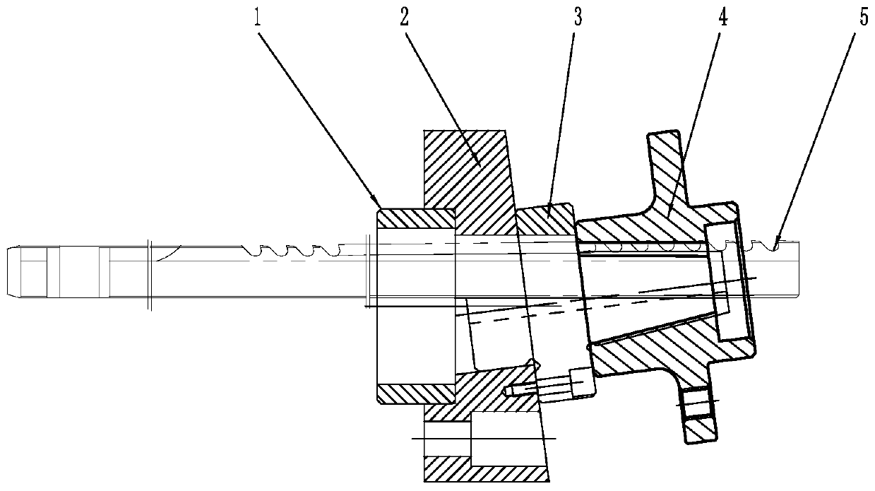
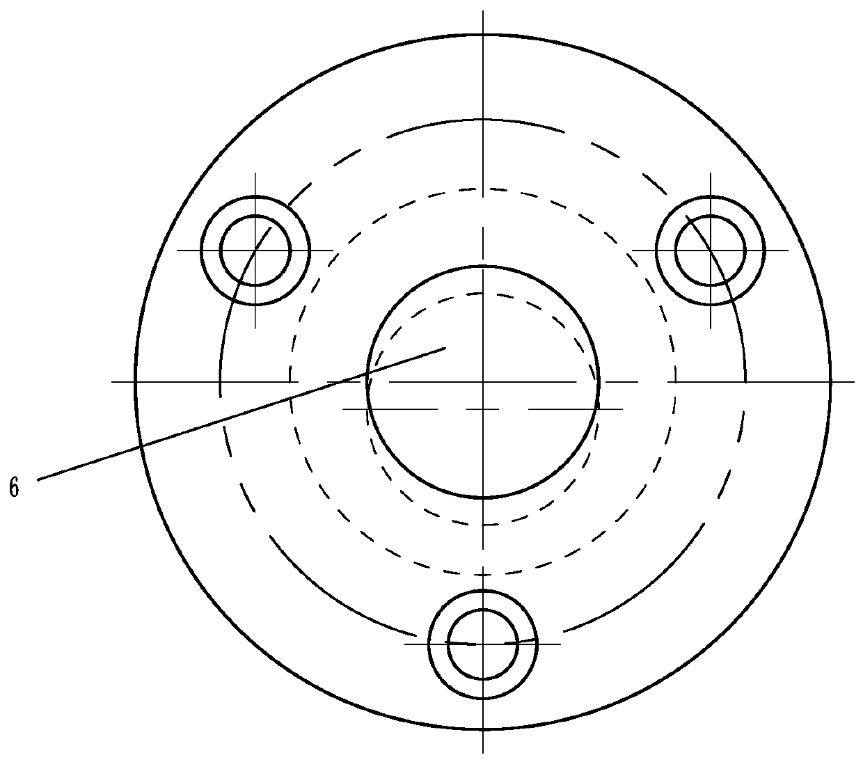
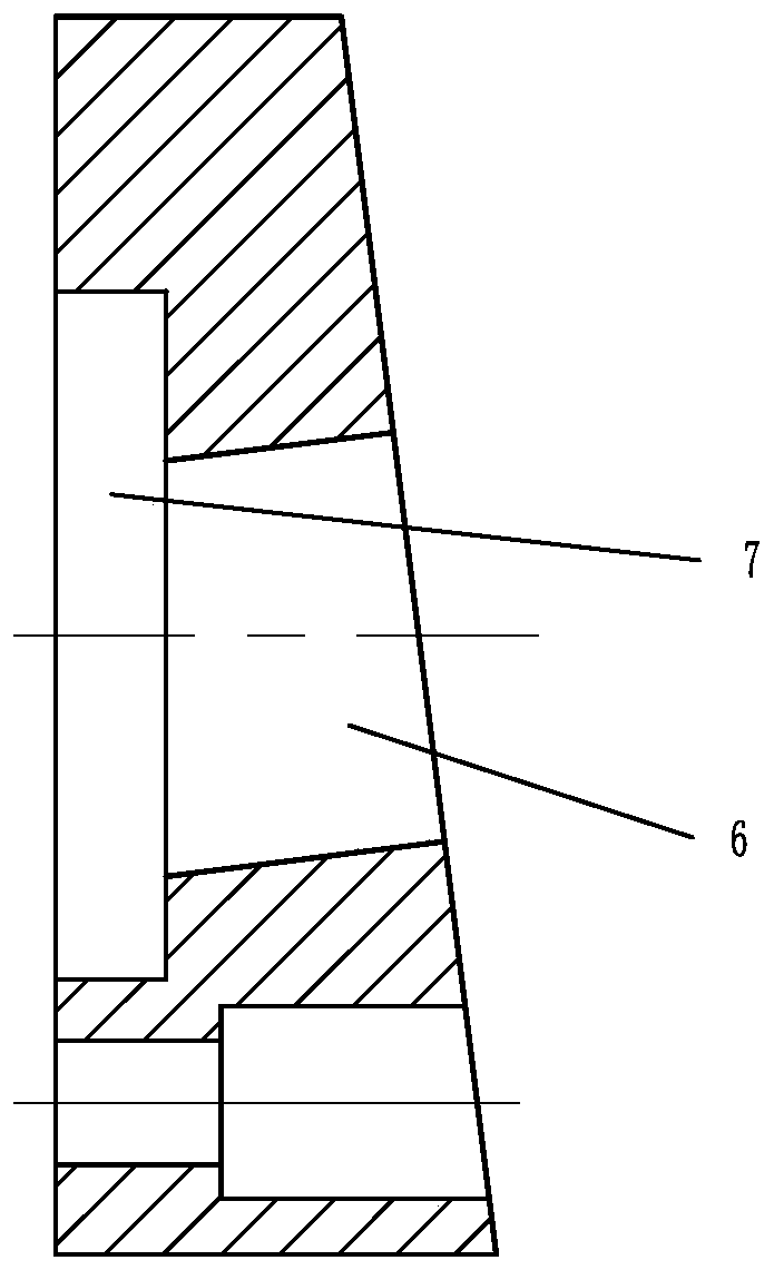
[0015] Embodiment: The tapered hole keyway processing fixture of the present invention, as attached figure 1 , attached figure 2 , attached image 3 , attached Figure 4 As shown, it includes a transition plate 2 as the installation main body; the front end face of the transition plate 2 is a slope, and the middle part is vertically provided with a guide hole 6; the rear end face of the transition plate 2 is a vertical surface, and a positioning hole 7 is vertically provided; The guide hole 6 is a through hole, the positioning hole 7 is a blind hole, and the guide hole 6 runs through the middle part of the hole bottom of the positioning hole 7; the positioning ring 1 is set in the positioning hole 7, and the positioning ring 1 It is a ring structure with an inner hole for the keyway broach 5 to pass through; the positioning ring 1 is partially inserted into the positioning hole 7, and the part exposed outside the positioning hole 7 cooperates with the outside to form the po...


PUM


Abstract

The invention provides a cone keyway machining fixture. The cone keyway machining fixture can quick position a workpiece to be processed and has higher position accuracy. The technical scheme is thatthe cone keyway machining fixture comprises a transit plate as a mounting main body; the front end face of the transit plate is a slope, and a guiding hole is formed perpendicularly in the middle of the front end face of the transit plate; the rear end face of the transit plate is a vertical face, and a positioning hole is formed perpendicularly in rear end face of the transit plate; the guiding hole is a through hole, the positioning hole is a blind hole, and the guiding hole passes through the middle of the bottom of the positioning hole; a positioning ring is arranged in the positioning hole; the positioning ring is of a ring-shaped structure; a part of the positioning ring is inserted into the positioning hole, and the part, out of the positioning hole, of the positioning ring fits with the external to form the positioning of the transit plate; a guiding sleeve is inserted in the guiding hole; and the middle section of the guiding sleeve is attached to the front end face of the transit plate, the rear section of the guiding sleeve is in a cylinder shape and inserted into the guiding hole, and the first section of the guiding sleeve is in a cone shape.

Description

technical field [0001] The invention relates to auxiliary tooling, in particular to a fixture for processing taper hole key grooves. Background technique [0002] For workpieces with inner conical holes, such as flange mounts in the motor industry, keyways are axially provided on the conical side walls of the inner conical holes, and the keyways are on the center plane of the whole, but inclined to the center line of the whole; therefore, When machining the keyway, special tooling is required to provide positioning for the keyway; in the traditional technology, the outer peripheral surface of the workpiece is clamped from the outside by the tooling to provide positioning for the keyway on the conical side wall of the inner conical hole. In this way, although The processing problem of the keyway is basically solved, but the workpiece is usually a casting, and the precision of the outer peripheral surface is usually not high. Therefore, as a positioning surface, the positionin...

Claims


Application Information

Patent Timeline
Patent Type & Authority Applications(China)
IPC IPC(8): B23Q3/18
Inventor 张敬国张寿海
Owner HENGDIAN GRP INNUOVO ELECTRIC
Why Eureka
Try Eureka