Anti-collision charging pile for new energy automobile and using method of anti-collision charging pile

A technology for new energy vehicles and charging piles, applied in electric vehicle charging technology, charging stations, electric vehicles, etc., can solve the problems of adjustment, height adjustment, poor applicability, etc.

Active Publication Date: 2019-05-17
福弼通科技有限公司
View PDF7 Cites 2 Cited by
  • Summary
  • Abstract
  • Description
  • Claims
  • Application Information

AI Technical Summary

Problems solved by technology

[0004] The purpose of the present invention is to provide an anti-collision charging pile for new energy vehicles and its use method, which can solve the problem of unavoidable problems caused by the driver's operation error when reversing the charging pile when using the traditional charging pile for new energy vehicles. The rear of the car hits the charging pile, which brings unnecessary losses to the charging pile or the new energy vehicle. Although the traditional charging pile also has a simple anti-collision protection structure, the anti-collision protection structure cannot be adjusted horizontally and vertically. Adjustment and height adjustment, so there is a problem of poor applicability

Method used


Image

  • Anti-collision charging pile for new energy automobile and using method of anti-collision charging pile
  • Anti-collision charging pile for new energy automobile and using method of anti-collision charging pile
  • Anti-collision charging pile for new energy automobile and using method of anti-collision charging pile

Examples


Embodiment Construction

[0033] The technical solutions of the present invention will be clearly and completely described below in conjunction with the embodiments. Apparently, the described embodiments are only some of the embodiments of the present invention, not all of them. Based on the embodiments of the present invention, all other embodiments obtained by persons of ordinary skill in the art without creative efforts fall within the protection scope of the present invention.

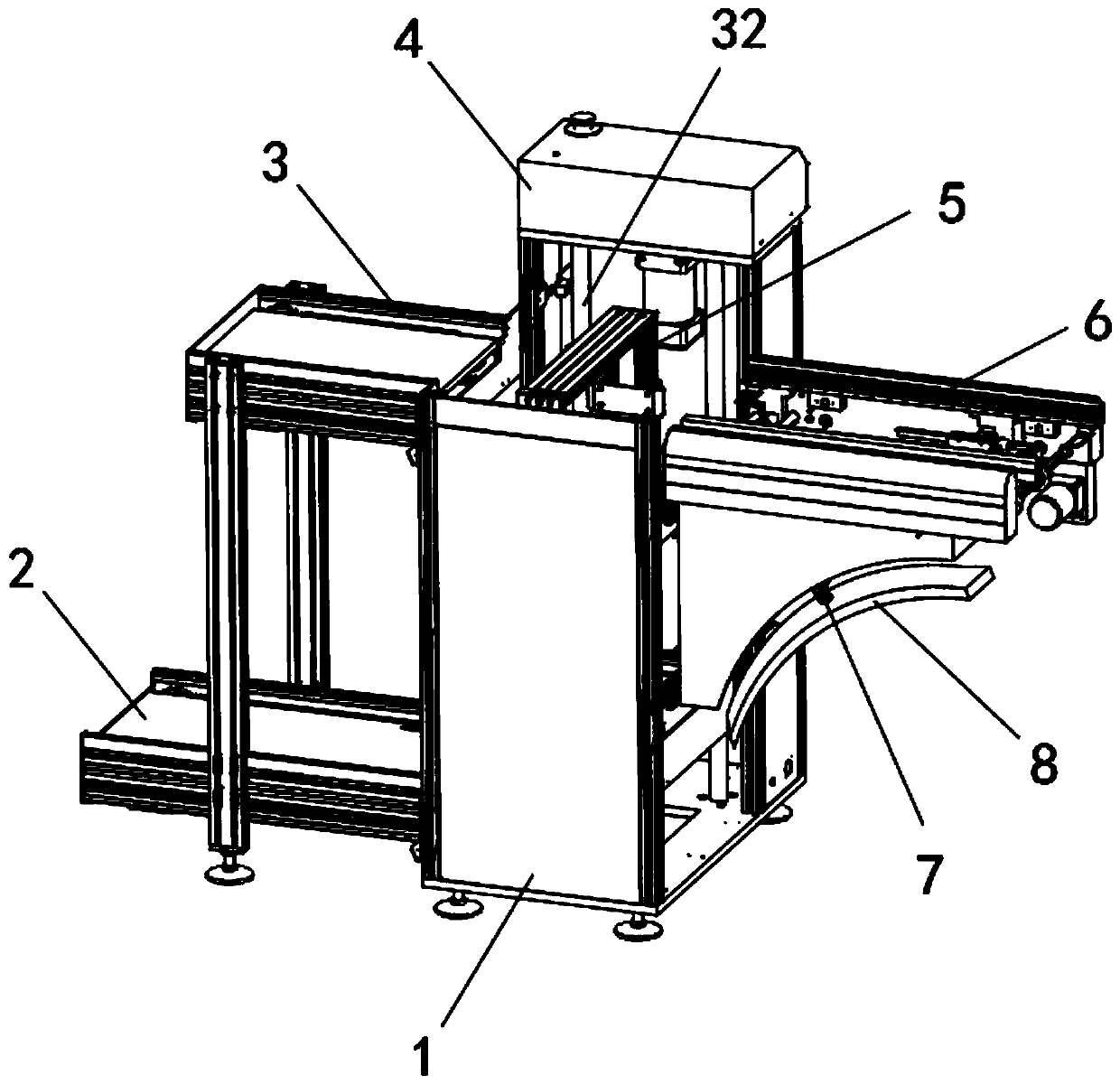
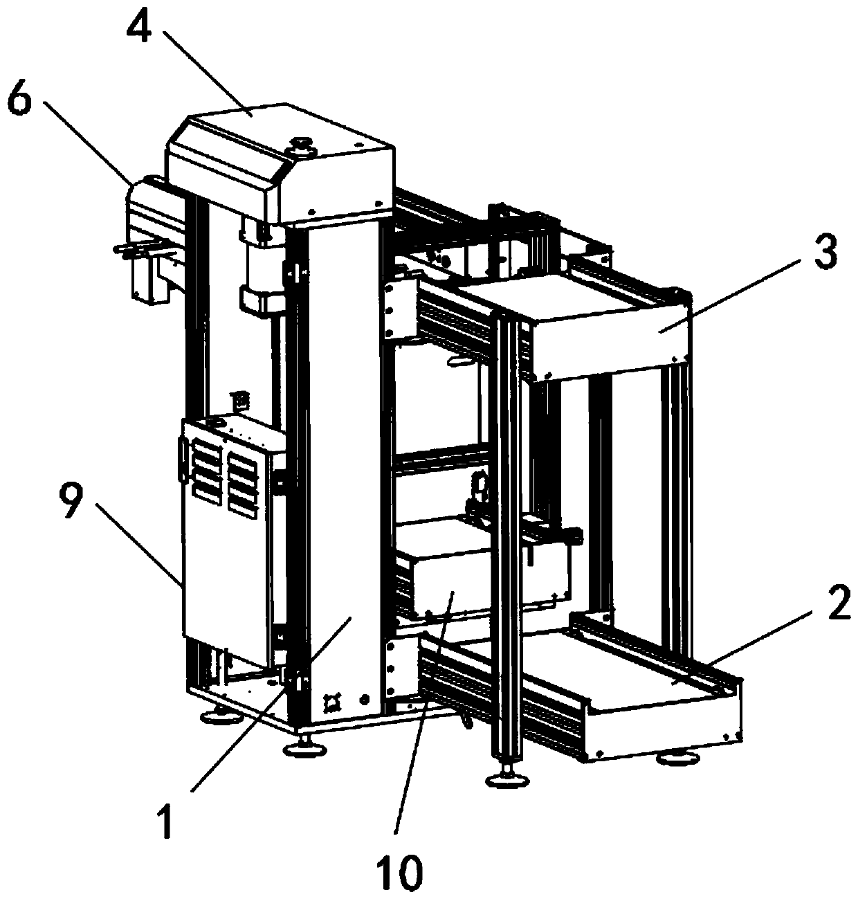
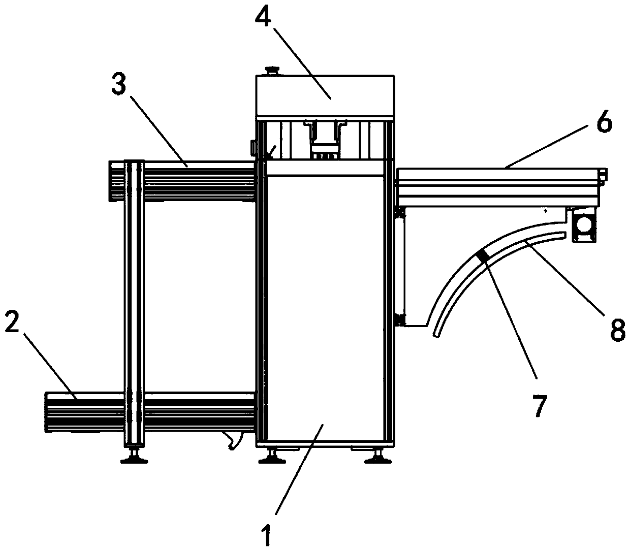
[0034] see Figure 1-8As shown, the charging pile for anti-collision new energy vehicles includes a bracket 1 and a top frame 3 on top of it. The top power supply 4 is installed on the top of the top frame 3, and a mounting frame 5 is installed inside the bracket 1, and the bottom side wall of the bracket 1 The bottom power supply 2 is installed on the top, the side frame 6 is welded and fixed on the top side wall of the support 1, and the PLC controller 9 is installed on the side wall of the support 1, and the bottom of th...


PUM


Abstract

The invention discloses an anti-collision charging pile for a new energy automobile and a using method of the anti-collision charging pile. The problems that during use of a traditional charging pilefor a new energy automobile, the tail of the automobile collides to the charging pile due to operation errors when a driver backs the automobile for charging, unnecessary loss is brought to the charging pile or the new energy automobile, although the traditional charging pile has a simple collision protection structure, the collision protection structure cannot be adjusted in the transverse direction and the longitudinal direction and cannot be adjusted either in the height direction, and thus, the applicability is not high are solved. The anti-collision charging pile for the new energy automobile comprises a support and a top frame positioned on the top of the support, a top power supply is installed on the top of the top frame, an installation frame is installed inside the support, a bottom power supply is installed on a side wall of the bottom of the support, a side frame is welded and fixed to a side wall of the top of the support, a PLC (programmable logic controller) is installedon a side wall of the support, and two penetrating rods located inside the support are connected to the bottom of the top power supply.

Description

technical field [0001] The invention relates to a charging pile, in particular to a charging pile for an anti-collision new energy vehicle and a using method thereof. Background technique [0002] The function of the charging pile is similar to that of the fuel dispenser in the gas station. It can be fixed on the ground or wall, and installed in the parking lot or charging station of public buildings and residential areas. It can charge various types of new energy vehicles according to different voltage levels. The input end of the charging pile is directly connected to the AC power grid, and the output end is equipped with a charging plug for charging new energy vehicles. [0003] However, when the existing charging piles for new energy vehicles are in use, it is inevitable that the driver will hit the rear of the car on the charging piles due to operational errors when charging in reverse, which will bring unnecessary damage to the charging piles or new energy vehicles. H...

Claims


Application Information

Patent Timeline
Patent Type & Authority Applications(China)
IPC IPC(8): B60L53/31B60L53/35B60L53/60
CPCB60L53/31B60L53/35B60L53/60F16F15/04Y02T10/70Y02T10/7072Y02T90/12
Inventor 叶萌胡传红
Owner 福弼通科技有限公司
Why Eureka
Try Eureka