Cable-stayed steel truss cooperative system bridge

A technology for steel trusses and bridges, applied in the field of cable-stayed steel truss cooperative system bridges, can solve the problems of cluttered vision, low bearing capacity, and many rods, and achieve the effect of improving wind resistance stability and good dynamic performance.

Active Publication Date: 2019-05-17
TONGJI UNIV ARCHITECTURAL DESIGN INST GRP CO LTD
View PDF4 Cites 2 Cited by
  • Summary
  • Abstract
  • Description
  • Claims
  • Application Information

AI Technical Summary

Problems solved by technology

[0004] However, the traditional truss bridge has dense members and unsatisfactory visual effects, mainly in the following aspects:
[0005] (1) There are many rods and the vision is messy;
[0006] (2) Under the stable control of the rod, the bearing force is small;
[0007] (3) The construction of the main span on the river is difficult;
[0008] (4) The cost is high and the economy is poor

Method used


Image

  • Cable-stayed steel truss cooperative system bridge

Examples


Embodiment 1

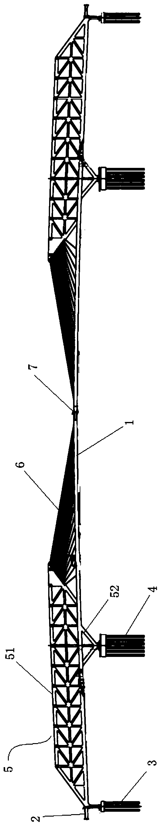
[0023] A cable-stayed steel truss collaborative system bridge, such as figure 1 As shown, the bridge includes a main bridge 1 and an approach bridge 2 connected to both ends of the main bridge 1. A transfer pier 3 is set at the junction of the main bridge 1 and the approach bridge 2, and two middle piers 4 are set in the middle of the main bridge 1. The distance between 3 and middle pier 4 is 160m, and the total span of main bridge 1 is 785m. Both ends of the main bridge 1 are provided with a steel truss cantilever beam 5 structure, including the parallelogram structure of the upper part 51 and the V-shaped structure of the lower part 52. There are cables 6 between the inner end of the upper part 51 and the main bridge 1. The main bridge 1 There are expansion joints and rigid hinges 7 in the middle to transmit longitudinal and transverse bending moments and shear forces, and release temperature forces.

[0024] Specifically:

[0025] The main bridge adopts a cable-stayed and cant...


PUM


Abstract

The invention relates to a cable-stayed steel truss cooperative system bridge. The cable-stayed steel truss cooperative system bridge comprises a main span and side spans, wherein a middle pier is arranged on the lower part of the main span; the cable-stayed steel truss cooperative system bridge is characterized in that steel truss cantilever beams are arranged at the side spans thereof; cables and a bridge deck are arranged at the inner ends of the steel truss cantilever beams and on the middle part of the main span. Compared with the prior art, the cable-stayed steel truss cooperative systembridge provided by the invention has the advantages as follows: through combination of the conventional steel truss girder bridge and the conventional cable-stayed bridge, the main span bridge deck supported by stay cables can be arranged under the condition that a towering bridge tower is not required to be arranged, the dynamic performance better than that of the conventional cable-stayed bridge under the same condition can be achieved, and the wind-resisting stability thereof is improved; the cable-stayed steel truss cooperative system bridge is especially suitable for a long-span bridge with an aviation height limit requirement.

Description

Technical field [0001] The invention relates to the technical field of bridges, in particular to a cable-stayed steel truss collaboration system bridge. Background technique [0002] There are many bridge structures suitable for 300~500m spans, including almost all bridges including steel truss girder bridges, cable-stayed bridges, suspension bridges and arch bridges. However, each bridge type has its natural conditions for bridge construction. If there are thrust arch bridges and ground anchor suspension bridges that are not suitable for soft soil foundation geological conditions, when there are strict height restrictions, conventional cable-stayed bridges, arch bridges and even suspension bridges will exceed the height restrictions due to the towers and arch ribs. Not suitable anymore. [0003] Relatively speaking, the steel truss girder structure is low in height and can be used for large and medium-span bridges with limited height requirements. However, the steel truss girder ...

Claims


Application Information

Patent Timeline
Patent Type & Authority Applications(China)
IPC IPC(8): E01D12/00
Inventor 徐利平
Owner TONGJI UNIV ARCHITECTURAL DESIGN INST GRP CO LTD
Why Eureka
Try Eureka