Refrigerator and refrigerating method thereof

A technology for refrigerators and cabinets, which is applied in the field of refrigerators and their refrigeration. It can solve problems such as easy occurrence of odors, lower volume ratio of freezer compartments, and longer defrosting time, so as to facilitate moisturizing and freshness, shorten defrosting time, and increase volume. rate effect

Active Publication Date: 2019-05-17
HEFEI MIDEA REFRIGERATOR CO LTD +2
View PDF6 Cites 3 Cited by
  • Summary
  • Abstract
  • Description
  • Claims
  • Application Information

AI Technical Summary

Problems solved by technology

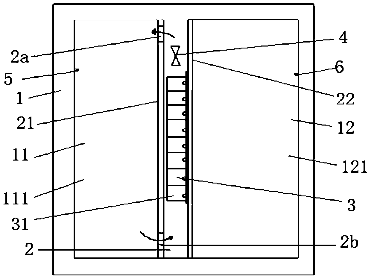
[0002] In ordinary single-system side-by-side refrigerators, the evaporator is set on the back of the freezer. This structural design has several disadvantages: Disadvantage 1. Refrigeration and refrigeration send the cold air in the freezer compartment to the freezer through the refrigeration air outlet. Refrigeration is carried out, and the cold air in the refrigerator returns to the freezer through the refrigerator return air vent at the same time. However, it is easy to cause odors
Disadvantage 2, refrigeration uses air cooling for refrigeration, which will reduce the humidity in the refrigerator, which is not conducive to food preservation and moisture retention. At the same time, the moisture in the refrigerator will condense on the evaporator in the freezer, which will lead to The amount of frost on the surface of the evaporator increases, resulting in a longer defrosting time, which affects energy consumption
Disadvantage three, since the evaporator in the freezer is placed at the back of the freezer, the cold energy will be lost to the external environment through the back of the freezer, resulting in loss of cold energy
In addition, both the freezing duct and the evaporator will occupy a lot of volume in the freezing room, resulting in a decrease in the volume ratio of the freezing room

Method used


Image

  • Refrigerator and refrigerating method thereof
  • Refrigerator and refrigerating method thereof
  • Refrigerator and refrigerating method thereof

Examples


Embodiment Construction

[0029] The specific implementation manners of the present invention will be further described in detail below in conjunction with the accompanying drawings and embodiments. The following examples are used to illustrate the present invention, but are not intended to limit the scope of the present invention.

[0030] In the description of the present invention, it should be noted that unless otherwise specified and limited, the terms "installation", "connection" and "connection" should be understood in a broad sense, for example, it can be a fixed connection or a detachable connection. Connected, or integrally connected; it can be mechanically connected or electrically connected; it can be directly connected or indirectly connected through an intermediary, and it can be the internal communication of two components. Those of ordinary skill in the art can understand the specific meanings of the above terms in the present invention in specific situations.

[0031] Such as figure ...


PUM


Abstract

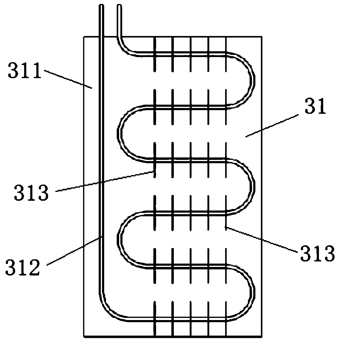
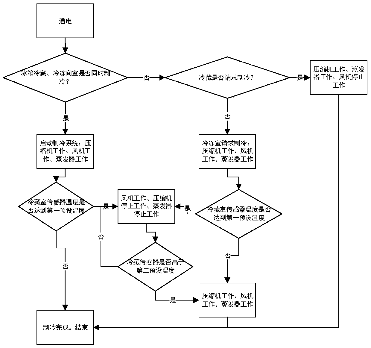
The invention relates to the technical field of refrigeration, and discloses a refrigerator and a refrigerating method thereof. The refrigerator comprises a box body, an interlayer and an evaporator,wherein a first chamber and a second chamber are constructed inside the box body correspondingly, the first chamber and the second chamber are arranged at intervals; the interlayer is arranged betweenthe first chamber and the second chamber, an air supply port and an air return port are constructed in the side wall of the interlayer correspondingly, wherein the interlayer and the first chamber form a refrigeration circulation loop through the air supply port and the air return port; the evaporator is arranged in the interlayer; and a part of cooling capacity released by the evaporator is transmitted to the first chamber through the air supply port to be used for refrigerating the first chamber, and the other part of the cooling capacity released by the evaporator is directly transferred to the second chamber through a heat exchange mode to be used for refrigerating the second chamber. The refrigerator has the advantages that the refrigeration efficiency is high, the occupied space issaved, and loss of the cooling capacity is reduced.

Description

technical field [0001] The invention relates to the technical field of refrigeration, in particular to a refrigerator and a refrigeration method thereof. Background technique [0002] In ordinary single-system side-by-side refrigerators, the evaporator is set on the back of the freezer. This structural design has several disadvantages: Disadvantage 1. Refrigeration and refrigeration send the cold air in the freezer compartment to the freezer through the refrigeration air outlet. Refrigeration is carried out, and the cold air in the refrigerator returns to the freezer through the refrigerator return air vent at the same time. However, this is easy to cause odors. Disadvantage 2, refrigeration uses air cooling for refrigeration, which will reduce the humidity in the refrigerator, which is not conducive to food preservation and moisture retention. At the same time, the moisture in the refrigerator will condense on the evaporator in the freezer, which will lead to The amount of...

Claims


Application Information

Patent Timeline
Patent Type & Authority Applications(China)
IPC IPC(8): F25D11/02F25D17/06F25D21/04F25D23/00F25D29/00
Inventor 盛庆赫王红娟何仁庶施红玉赵云常见虎
Owner HEFEI MIDEA REFRIGERATOR CO LTD
Why Eureka
Try Eureka