Cabling machine

A cable forming machine and cable technology, applied in the direction of cable/conductor manufacturing, circuits, electrical components, etc., can solve problems such as troubles, loss of support for winding drums, etc.

Pending Publication Date: 2019-05-17
FOSHAN YUEJIAXIN WIRE & CABLE
View PDF0 Cites 6 Cited by
  • Summary
  • Abstract
  • Description
  • Claims
  • Application Information

AI Technical Summary

Problems solved by technology

A general cable forming machine includes a hollow shaft, a back-twisting mechanism, a hurdle, a circular pay-off reel, a splitter board, a main formwork frame, a yarn wrapping head, a wrapping head formwork frame, a traction wheel and a take-up device (that is, a winding device) , and in the wire take-up device, the reel i

Method used


Image

  • Cabling machine
  • Cabling machine
  • Cabling machine

Examples


Embodiment Construction

[0027] The present invention provides a cable forming machine. In order to make the purpose, technical solution and effect of the present invention clearer and clearer, the present invention will be further described in detail below with reference to the accompanying drawings and examples. It should be understood that the specific embodiments described herein are only used to explain the present invention, but not to limit the present invention.

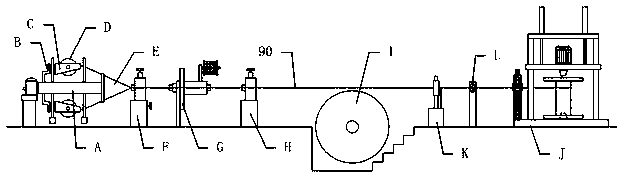
[0028] In this paper, rear refers to the direction of cable movement, i.e. figure 1 The right side in the middle, the front and back are reversed.

[0029] see Figure 1-9 , a cable forming machine provided by the present invention, comprising a hollow shaft A, an untwisting mechanism B, a hurdle C, a circular pay-off reel D, a splitter plate E, a main formwork frame F, a yarn wrapping head G, and a wrapping headform Frame H, traction wheel I, take-up device J, said take-up device J includes a base J1, a reel J2 vertically arranged...


PUM


Abstract

The invention provides a cabling machine comprising a hollow shaft, a back-twist mechanism, a hurdle, a circular pay-off spool, a branching board, a main mould frame, a yarn covering head, a winding head mould frame, a traction wheel and a wire take-up device, wherein the wire take-up device comprises a base, a take-up reel vertically arranged on the base, an active chuck and a driven chuck respectively clamped on the upper and lower ends of the take-up reel, a first motor driving the active chuck to rotate, and a cutting mechanism disposed in front of the take-up reel; the driven chuck is disposed on the base, the active chuck and the first motor are disposed on a lifting plate that is driven by a first lifting mechanism to operate; and the cutting mechanism is used for cutting the cable.The cabling machine can avoid the loss of support of the take-up reel during the replacement process and is convenient to use.

Description

technical field [0001] The invention relates to the technical field of electric wire production, in particular to a cable forming machine. Background technique [0002] The cable forming machine is a wire and cable equipment used for cable forming and armoring of multi-core rubber-sheathed cables, plastic cables, cross-linked cables, telephone cables, and control cables of various cross-sections. A general cable forming machine includes a hollow shaft, a back-twisting mechanism, a hurdle, a circular pay-off reel, a splitter board, a main formwork frame, a yarn wrapping head, a wrapping head formwork frame, a traction wheel and a take-up device (that is, a winding device) , and in the wire take-up device, the reel is generally set horizontally. When replacing the reel, it is necessary to pull out the rewinding chucks at both ends of the reel. After the rewinding chuck is pulled out, the reel will lose its support. Therefore, it is cumbersome to hold the reel first with a for...

Claims


Application Information

Patent Timeline
IPC IPC(8): H01B13/00H01B13/02B65H54/54B65H54/44B65H67/04
Inventor 王振远梁柳冰吕志发龙乃生
Owner FOSHAN YUEJIAXIN WIRE & CABLE
Why Eureka
Try Eureka