
Numerical control stretch bending machine tool and clamping force monitoring method of round head fixture thereof

A technology of clamping force and round head clamp, which is applied in the field of CNC machine tools, can solve the problems of workpiece clamping, high energy consumption, and heavy clamping marks of the workpiece, and achieve the effects of protecting the workpiece, saving energy, and avoiding excessive energy consumption

Active Publication Date: 2019-05-21
HEFEI UNIV OF TECH
View PDF7 Cites 0 Cited by
  • Summary
  • Abstract
  • Description
  • Claims
  • Application Information

AI Technical Summary

Problems solved by technology

[0004] Aiming at the existing technical problems, the present invention provides a numerically controlled stretch bending machine tool and a method for monitoring the clamping force of its round head fixture, which solves the problem that the existing stretch bending machine tool fixtures set the pressure of the hydraulic cylinder based on experience and cannot monitor the fixture in real time Clamping force, resulting in excessive energy consumption due to excessive clamping force, excessive clamping marks on the workpiece, and the problem of clamping the workpiece

Method used


Image

  • Numerical control stretch bending machine tool and clamping force monitoring method of round head fixture thereof
  • Numerical control stretch bending machine tool and clamping force monitoring method of round head fixture thereof
  • Numerical control stretch bending machine tool and clamping force monitoring method of round head fixture thereof

Examples


Embodiment 1

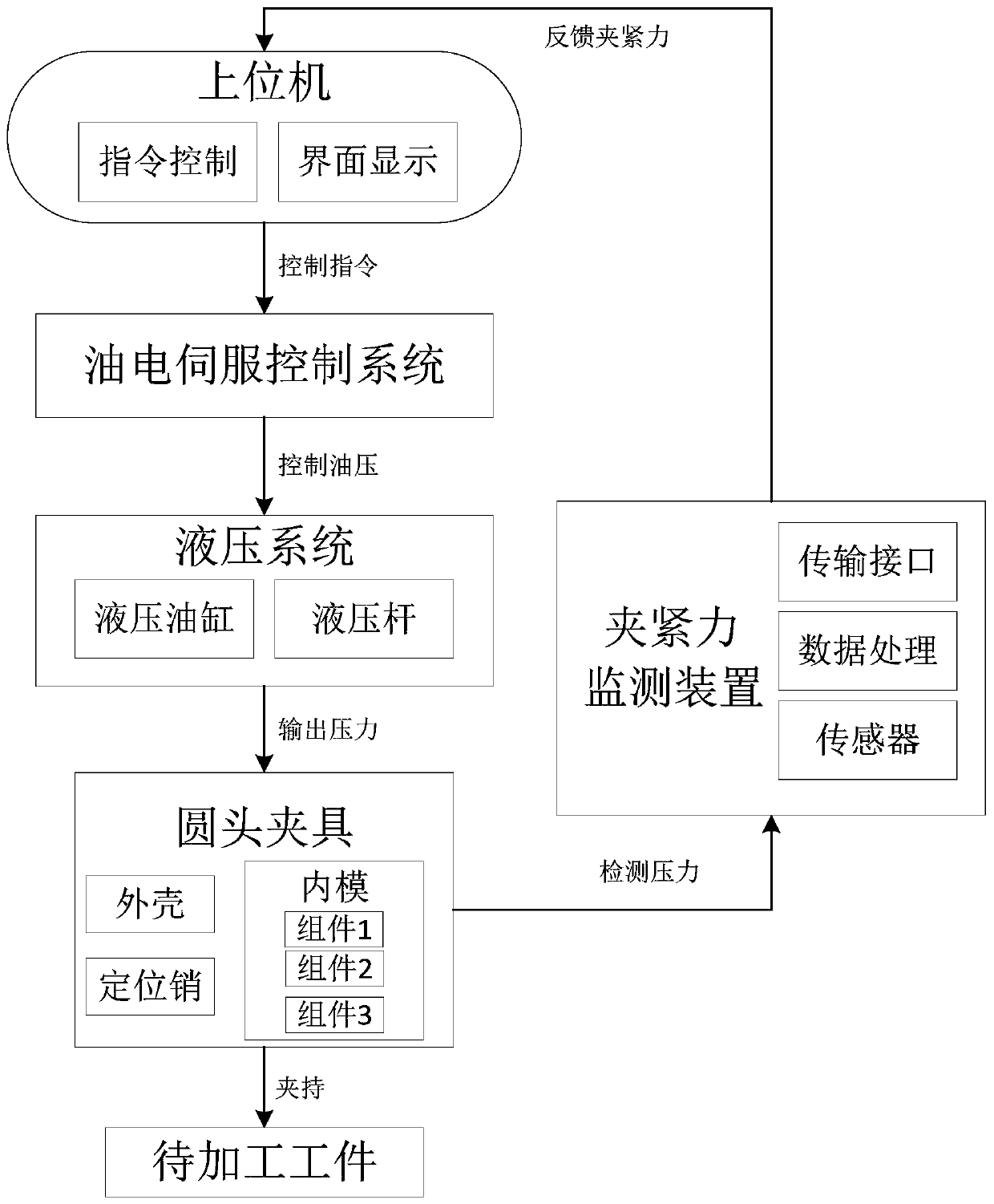
[0055] see figure 1 as well as figure 2 , this embodiment provides a numerically controlled stretch bending machine tool, which includes a round head fixture, a hydraulic system, and a clamping force monitoring device, and may also include a host computer and a hybrid electric servo control system. The CNC stretch bending machine is used to stretch and bend workpieces, such as stretch bending various steel pipes, square pipes, H-beams, I-beams, channel steels, angle irons, flat irons and aluminum profiles.

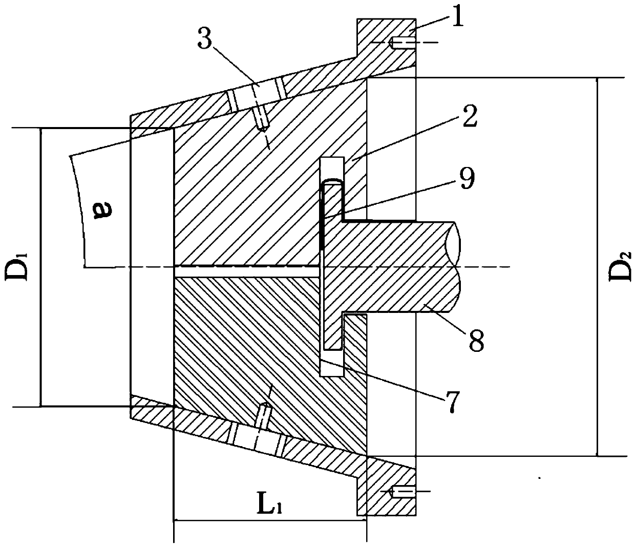
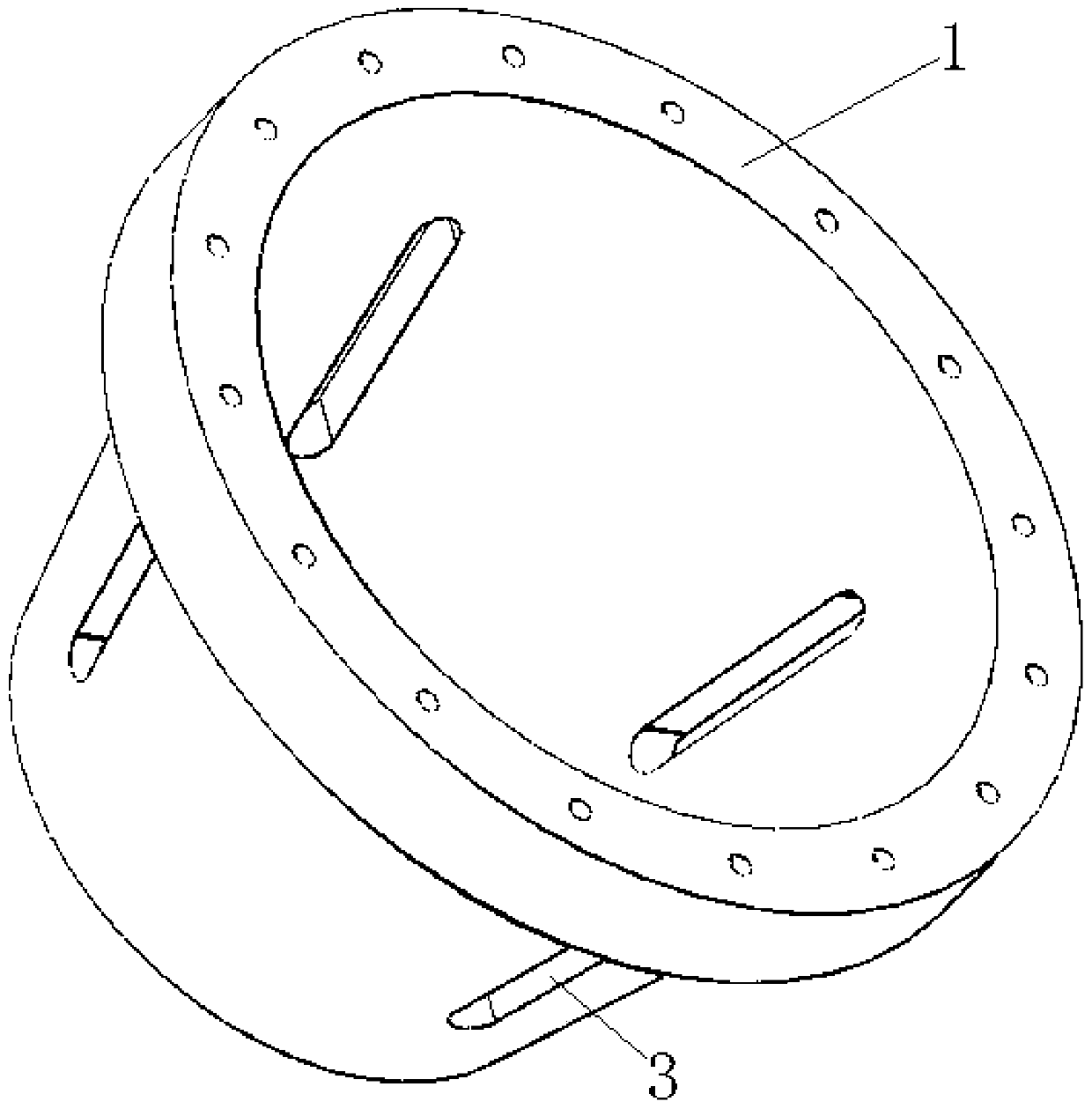
[0056] The round head clamp is used to clamp the workpiece and can be installed on other fixed structures of the CNC stretch bending machine. The round head clamp includes a shell 1, an inner mold 2 and a positioning member. The inner mold 2 is arranged in the shell 1. The positioning piece is used to position the inner mold 2 in the shell 1, and preferably a positioning pin. Such as image 3 As shown, the outer contour of the shell 1 is in the shape of a truncated con...

Embodiment 2

[0077] read on figure 2 , this embodiment provides a clamping force monitoring device for a round-head fixture, which is independent from the numerically controlled stretch bending machine tool of Embodiment 1 and applied to the numerically controlled stretch bending machine tool. What needs to be explained here is that when applying the clamping force monitoring device of the round end fixture in this embodiment, the CNC stretch bending machine tool may not include the clamping force monitoring device, that is, the clamping force monitoring device of the round end fixture shall be regarded as an independent product It can also be used in other CNC stretch bending machine tools. Wherein, the clamping force monitoring device of the round head fixture includes a detection mechanism, a cone angle calculation unit and a clamping force calculation unit.

[0078] The detection mechanism is set in the installation groove 7 and is used to detect the pressure F between the hydraulic ...

Embodiment 3

[0081] This embodiment provides a method for monitoring the clamping force of a round head fixture, which is applied to the numerically controlled stretch bending machine tool in Embodiment 1, and includes the following steps:

[0082] 1. Detect the pressure F between the hydraulic rod 8 and the inner mold 2 0 ;

[0083] 2. Calculate the cone angle α of the conical structure, and the calculation formula is α=tan -1 [D 2 -D 1 / 2*L 1 ]; where D 1 is the radius of the top surface of the cone structure, D 2 is the radius of the bottom surface of the cone structure, L 1 is the height of the frustum structure;

[0084] 3. Calculate the clamping force F between the inner mold 2 and the workpiece 3 , and the calculation formula is F 3 =F 0 * cot α.

[0085] The effect of the method for monitoring the clamping force of the round end fixture provided in this embodiment is the same as that of the device for monitoring the clamping force of the round end fixture in Embodiment 2...


PUM


Abstract

The invention discloses a numerical control stretch bending machine tool and a method for monitoring clamping force of a round head fixture of the numerical control stretch bending machine tool. The numerical control stretch bending machine tool comprises the round head fixture, a hydraulic system and a clamping force monitoring device; the round head fixture comprises a housing, an inner mold anda positioning piece; the inner mold comprises a component I, a component II and a component III; the component I and the component II enclose a notch structure; the component III is inserted into a notch of the notch structure; the component III and the component I form a clamping space; the hydraulic system comprises a hydraulic rod and a hydraulic oil cylinder; the hydraulic rod enables the component I, the component II and the component III to form self-locking so as to clamp a workpiece in the clamping space; and the clamping force monitoring device comprises a sensor for detecting the pressure between the hydraulic rod and the inner mold and a data processing module for calculating the clamping force between the inner mold and the workpiece. According to the invention, workpieces with different shapes and sizes can be clamped, and the clamping force can be monitored in real time, so that energy is saved, and the workpieces are protected at the same time.

Description

technical field [0001] The invention relates to a numerically controlled stretch bending machine tool in the technical field of numerically controlled machine tools, and also relates to a method for monitoring the clamping force of a round head clamp. Background technique [0002] Stretch bending is a forming method in which the CNC stretch bending machine uses its fixtures and molds to bend the workpiece to be formed into a workpiece with a certain curvature, shape and size. It is widely used in cold bending of various steel pipes, square pipes, and H-beams with sections below 500mm. , I-beam, channel steel, angle iron, flat iron and aluminum profiles. [0003] The fixture is an important part of the CNC stretch bending machine tool, and its main function is to clamp the workpiece to be processed. At present, the fixtures of stretch bending machine tools are usually square fixtures, and the fixtures of corresponding sizes are designed according to the external dimensions o...

Claims


Application Information

Patent Timeline
Patent Type & Authority Applications(China)
IPC IPC(8): B21D7/06B21D43/00B21C51/00
CPCB21D7/02B21D7/12B21D11/02G05B2219/41273G05B2219/36203G05B19/182
Inventor 周丽华曹振鑫陈梁玉宋怀昊卜晓珍余春生
Owner HEFEI UNIV OF TECH
Learn More