Service robot with motion control device

A motion control device and technology for service robots, applied in the field of service robots, can solve the problems of unstable movement of robots, inconvenient steering adjustment, small bearing capacity, etc., and achieve the effects of convenient steering, increasing viewing angle, and reducing friction.

Active Publication Date: 2019-05-21
创泽智能机器人集团股份有限公司
View PDF14 Cites 12 Cited by
  • Summary
  • Abstract
  • Description
  • Claims
  • Application Information

AI Technical Summary

Problems solved by technology

[0004] However, the service robot provided in the above technical solution still has many disadvantages when it is actually used, such as the robot is unstable when moving, it is not easy to adjust the steering, and it has few functions and small bearing capacity.

Method used


Image

  • Service robot with motion control device
  • Service robot with motion control device
  • Service robot with motion control device

Examples


Embodiment 1

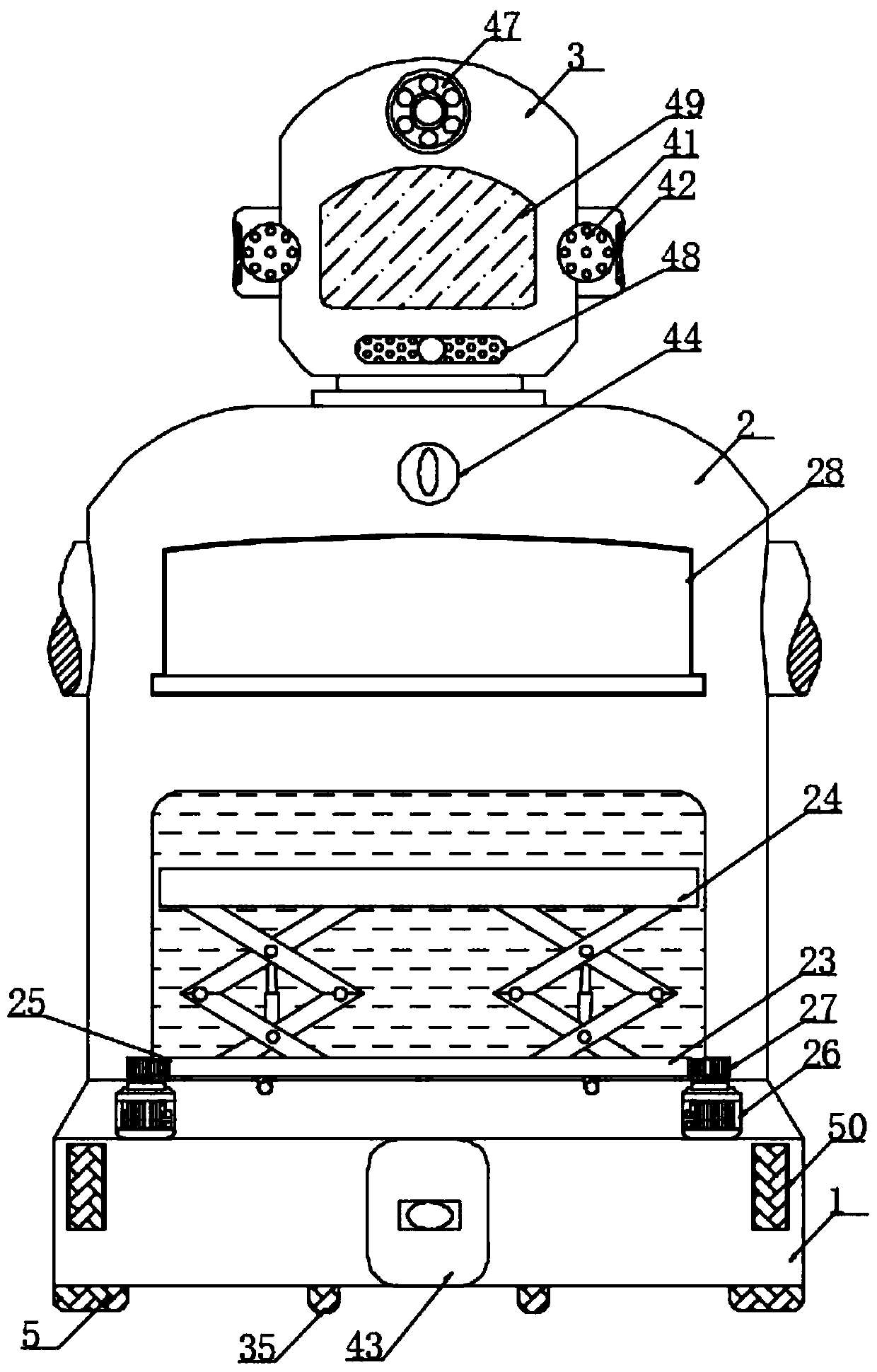
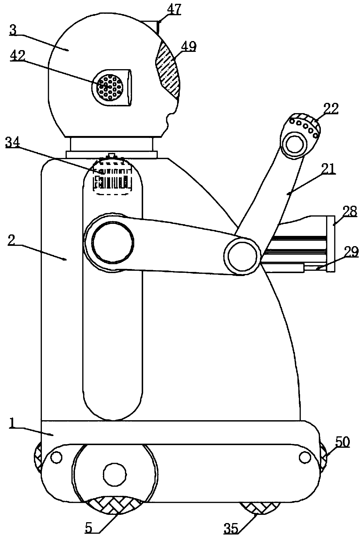
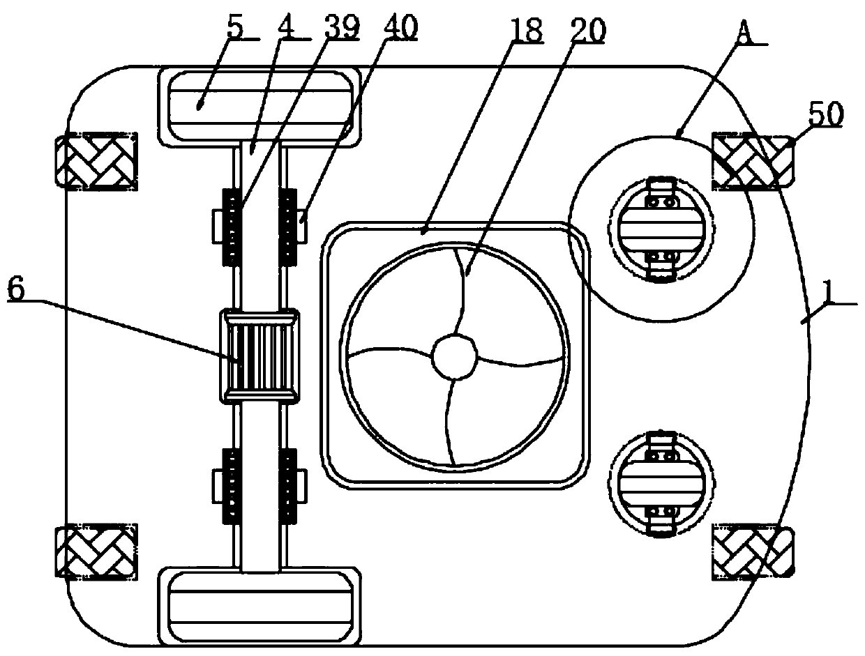
[0033] according to Figure 1-8 A service robot with a motion control device shown includes a base 1, the top of the base 1 is fixedly connected to an organic body shell 2, and the top of the body shell 2 is rotatably connected to a machine head part 3, and the base 1 The bottom is provided with a first groove, and the side of the bottom of the base 1 away from the first groove is provided with two symmetrically distributed second grooves, and a third groove is arranged between the first groove and the second groove. groove, the first groove is provided with a drive shaft 4, the two ends of the drive shaft 4 are fixedly connected with driving wheels 5, the middle part of the drive shaft 4 is provided with a first gear 6, and the base 1 is provided with There is a cavity, the first motor 8 is fixedly connected in the cavity, the output shaft of the first motor 8 is provided with a reducer 9, the output shaft of the reducer 9 is provided with a worm 10, and the worm 10 is connec...

Embodiment 2

[0038] according to Figure 1-6 As shown in a service robot with a motion control device, the steering mechanism includes a driven wheel 35, and a connecting rod 36 is rotatably connected to the axis of the driven wheel 35, and both sides of the connecting rod 36 pass through a limit rod 37, the top of the limit rod 37 is fixedly connected with the support rod 12, the outer side of the limit rod 37 is covered with a spring 38, and the spring 38 is arranged between the support rod 12 and the connecting rod 36, and the support rod 12 Balls are provided at the junction with the annular slide rail 11. By setting two driven wheels, the stability of the movement of the robot is improved. The junction of the support rod 12 and the annular slide rail 11 is provided with balls to reduce friction and enable the robot to turn flexibly. The limit rod 37 runs through the connecting rod 36 and cooperates with the spring 38, which is conducive to buffering and shock absorption, and improves ...


PUM


Abstract

The invention discloses a service robot with a motion control device, and in particular, relates to the field of robots. The service robot comprises a base; the top of the base is fixedly connected with a machine body shell; the top end of the machine body shell is rotationally connected with a machine head part; a first groove is formed in the bottom of the base; and a second groove is formed inthe side, far from the first groove, of the bottom of the base. A first motor drives a connecting worm rod to engage with a first gear to enable a driving shaft to drive a driving wheel; during steering, a second motor drives a third gear to engage with a second gear, so that a rotating rod drives a support rod to rotate in an annular slide rail to conveniently adjust the direction of a steering mechanism; a first electric push rod pushes a frame plate to descend to enable a sucker to contact with the ground; through work of an air extracting pump, the sucker is tightly sucked on the ground, so that the robot is fixed; after an output shaft of a third motor drives a fourth gear to engage with a rack to push out a support plate, an extension platform in unfolded to provide a placing tray; and an output shaft of a second electric push rod pushes out a storage drawer to conveniently collect objects.

Description

technical field [0001] The invention relates to the field of robots, and more specifically, the invention relates to a service robot with a motion control device. Background technique [0002] Today, with the development of modern science and technology, robots have become a new type of production tool and auxiliary tool for human beings. It has been applied in many aspects of daily life and is gradually playing an increasingly important role. It has shown great advantages in reducing human labor intensity and improving human production efficiency. [0003] The Chinese patent application publication number CN 108839030 A discloses a service robot, the head of which can be vertically and movably arranged on the upper end of the torso; There is a rotating shaft; an extension rod is fixedly connected to the side wall of the rotating shaft, and a camera is fixedly connected to the end of the extending rod away from the rotating shaft, and the shooting direction of the camera fa...

Claims


Application Information

Patent Timeline
Patent Type & Authority Applications(China)
IPC IPC(8): B25J5/00B25J9/00B25J9/16B25J19/00B25J11/00
Inventor 李庆民李延硕刘春晖王杰邵红臣郑华
Owner 创泽智能机器人集团股份有限公司
Why Eureka
Try Eureka