Grooving machine

A slotting machine and casing technology, applied in the field of building decoration tools, can solve problems such as damage to the walls on both sides of the groove, reduce the flatness of the groove, and damage the wall, so as to save production costs and use costs, and improve Flatness, damage reduction effect

Active Publication Date: 2019-05-21
TIANJIN ERJIAN WATER & ELECTRICAL INSTALLATION ENG
View PDF9 Cites 8 Cited by
  • Summary
  • Abstract
  • Description
  • Claims
  • Application Information

AI Technical Summary

Problems solved by technology

[0004] However, when it is necessary to slot on a wall with a loose internal structure and an easy-to-crack exterior (such as BLP light-weight wall), if a slotting machine similar to the above is used for slotting, due to the large width of the slotting knife, directly Grooving in the wall is easy to cause damage to the walls on both sides of the groove, which not only reduces the flatness of the groove, but also causes damage to the wall

Method used


Image

  • Grooving machine
  • Grooving machine
  • Grooving machine

Examples


Embodiment

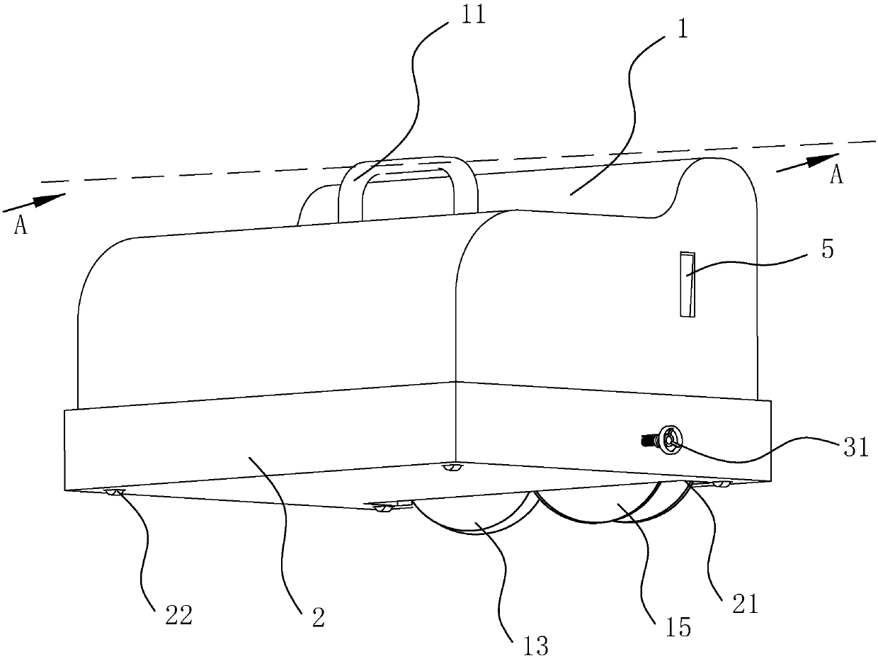
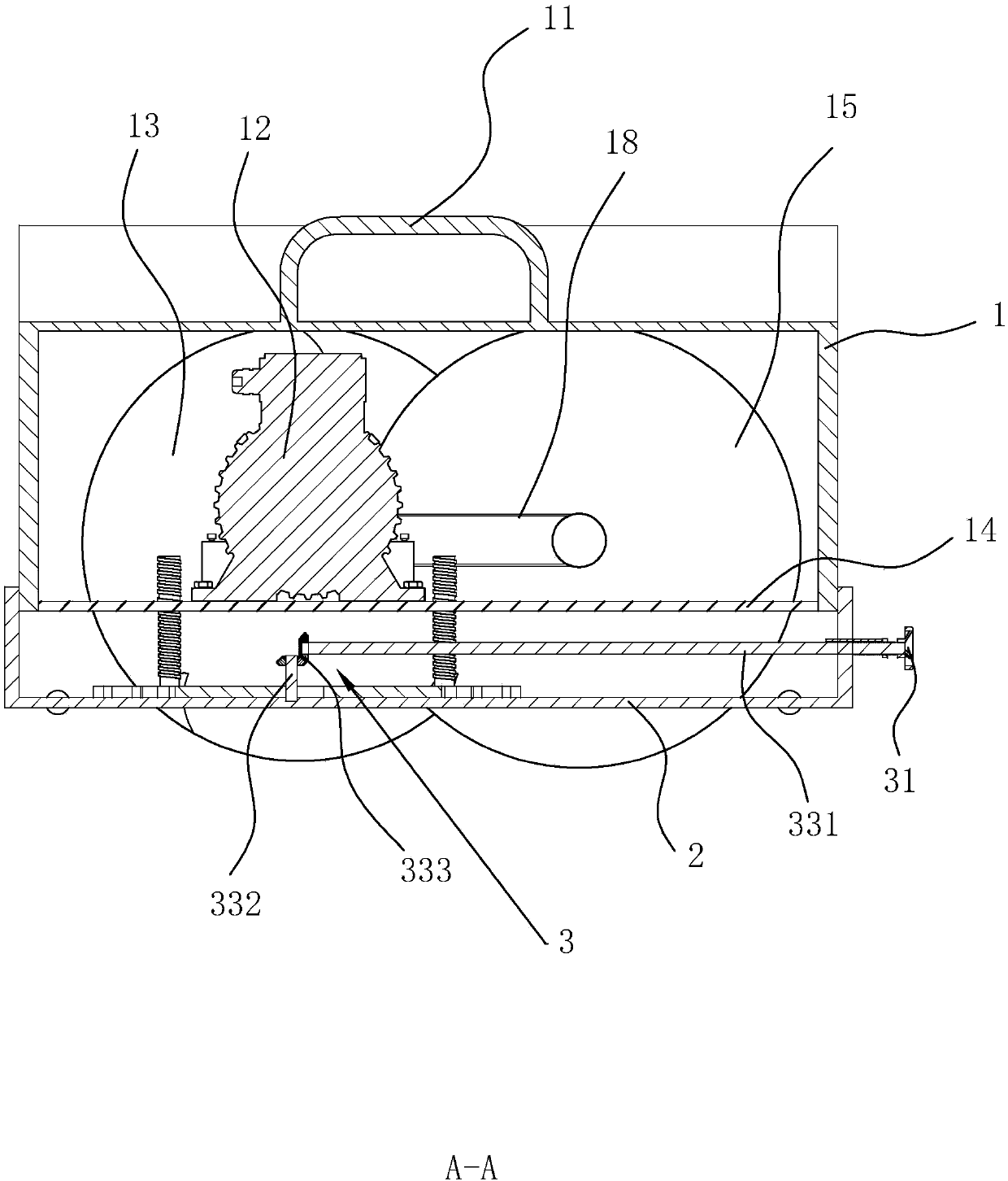
[0040] A slotting machine, refer to figure 1 and figure 2, comprising a casing 1 and a handle 11 connected to the outside of the casing 1, a driving motor 12 is installed in the casing 1, and a circular slotting knife 13 is installed at the end of the rotating shaft of the motor 12, and the rotating direction of the slotting knife 13 is consistent with the rotating shaft of the motor Vertical, and part of the groove knife 13 protrudes from the bottom plate 14 of the casing 1 . When carrying out the slotting operation, the operator holds the handle 11 to make the bottom plate 14 of the casing 1 fit the wall, the part of the slotting knife 13 protruding from the casing 1 cuts off the wall, and the slotting machine moves along the slotting direction on the wall. Move, so that slot cutter 13 excavates the slot on the wall smoothly.

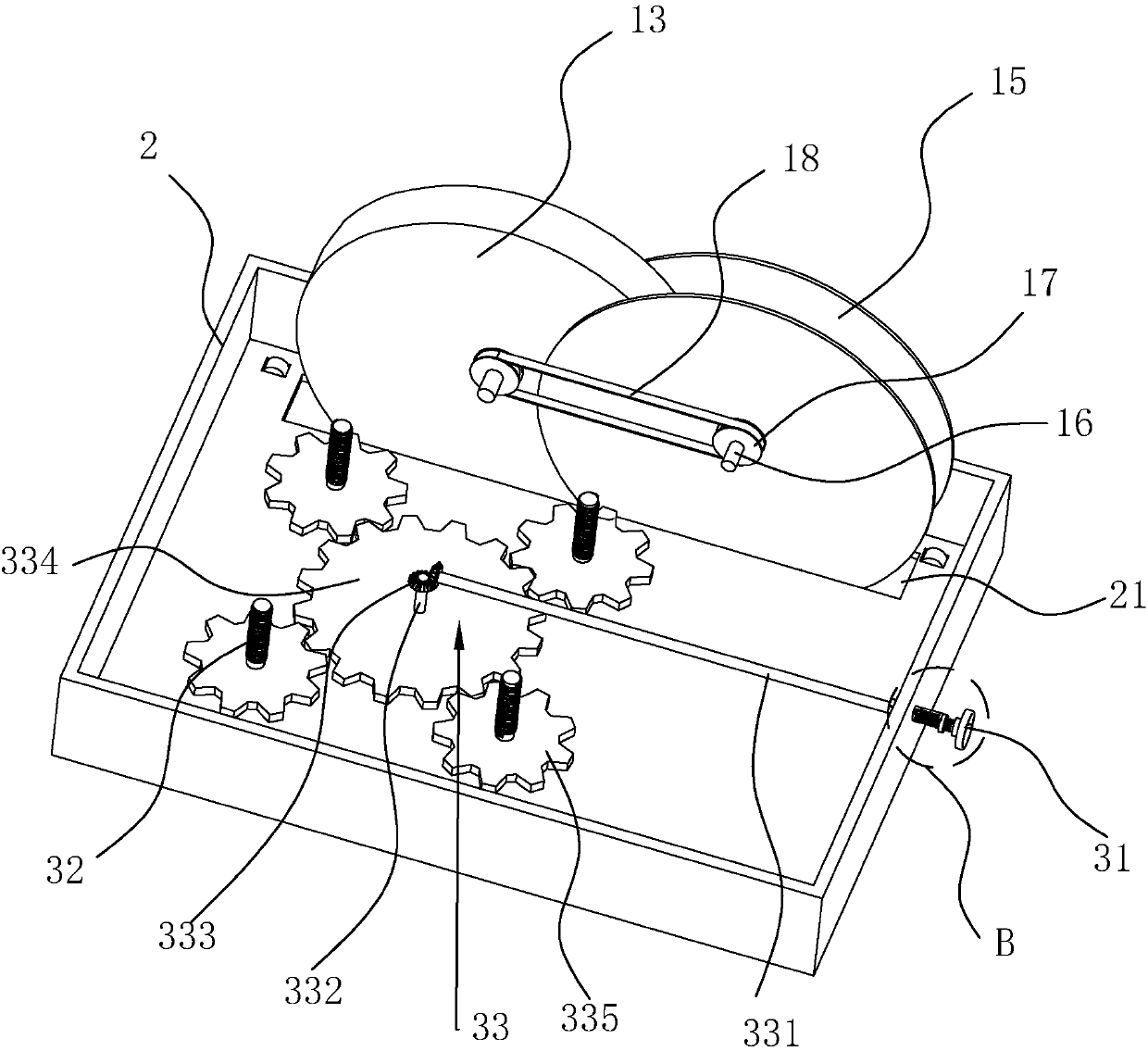
[0041] refer to figure 2 and image 3 Slotted saw blades 15 are attached to the slotted knives 13 on both sides of the slotted knife 13, and th...


PUM


Abstract

The invention relates to a grooving machine which comprises a machine shell. A motor is arranged in the machine shell. A groove cutter is arranged at the end of a rotating shaft of the motor. Groovingsaw blades are arranged on the two sides of the groove cutter correspondingly. The two saw blades are connected with the inner side wall of the machine shell through two first rotating rods correspondingly. One end of each first rotating rod is fixedly connected with the corresponding saw blade, and the other ends of the first rotating rods are rotationally connected with the inner side wall of the machine shell. The first rotating rods are parallel to the rotating shaft of the motor. A drive part used for driving the saw blades to rotate in the direction the same as that of the groove cutteris arranged in the machine shell. According to the principle that the smaller the thickness of a cutting cutter is, the smaller the stress damage generated to cutting objects is, the grooving saw blades are arranged on the two sides of the groove cutter, and therefore when a wall is grooved, the saw blades firstly form grooves in the wall, then the groove cutter is utilized for crushing the position, between the two grooves, of the wall along with movement of the grooving machine, operation that a groove cutter with the width conforming to that of a channel is utilized for direct grooving isavoided, and therefore the flatness of the positions, on the two sides of the channel, of the wall can be improved obviously, and then damage to the positions, on the two sides of the channel, of thewall in the grooving process is reduced.

Description

technical field [0001] The invention relates to a building decoration tool, in particular to a slotting machine. Background technique [0002] When building and decorating houses, we often encounter construction operations that require slotting on walls or hard ground. Traditional slotting is done by hand. With the development of society, people began to use electric hammers to assist the drilling After that, people have proposed a slotting machine dedicated to slotting. [0003] The invention patent with the notification number CN206170356U discloses a slotting machine, which includes a casing and a slotting knife installation shaft. The main motor is mechanically connected to the slotting knife installation shaft in the casing, and a feed roller is rotatably connected to the casing. , the axis of the feed roller is arranged parallel to the axis of the installation shaft of the groove cutter, a geared motor is fixedly connected to the casing, and the output shaft of the ge...

Claims


Application Information

Patent Timeline
Patent Type & Authority Applications(China)
IPC IPC(8): B28D1/06B28D7/00
Inventor 田来胡金檩杨成艳常顺钱卫刚
Owner TIANJIN ERJIAN WATER & ELECTRICAL INSTALLATION ENG
Why Eureka
Try Eureka