A high-efficiency vomiting receiving device

A receiving device, high-efficiency technology, applied in garbage collection, household appliances, garbage cans, etc., can solve the problems of pollutants or garbage hanging on the connecting rod, unable to take care of daily use, unable to place garbage bags, etc., to avoid lifting Garbage can or bent over, avoid smell, outer barrel and inner barrel stable effect

Active Publication Date: 2021-06-22
THE AFFILIATED HOSPITAL OF QINGDAO UNIV
View PDF8 Cites 1 Cited by
  • Summary
  • Abstract
  • Description
  • Claims
  • Application Information

AI Technical Summary

Problems solved by technology

[0002] The existing medical vomiting receiving device is generally an ordinary garbage can, and there are the following problems in use: 1. The operation is troublesome. First, it is necessary to open the cover or step on the pedal to open the garbage can, and then align the mouth of the garbage can and carry out the operation. Vomiting, so once you vomit immediately after opening the cover, it will cause pollution; 2. Generally, the height of the trash can is not enough, you need to lift the trash can or bend over to avoid splashing of vomit, which is very laborious; 3. Once the trash can is overturned , the vomit will pour out; 4. If you forget to close the cover, the vomit will emit odor
[0004] 1. The improved structure can only be opened by pulling up the auxiliary cylinder. Although it is convenient to hug the trash can for vomiting, it cannot be opened by stepping on it like a traditional trash can, so it cannot be used for daily use;
[0005] 2. Due to the curved structure of the connecting rod, it is not only impossible to place garbage bags, but also makes it easier for pollutants or garbage to hang on the connecting rod, making it difficult to clean; therefore, it is necessary to improve

Method used


Image

  • A high-efficiency vomiting receiving device
  • A high-efficiency vomiting receiving device
  • A high-efficiency vomiting receiving device

Examples


Embodiment Construction

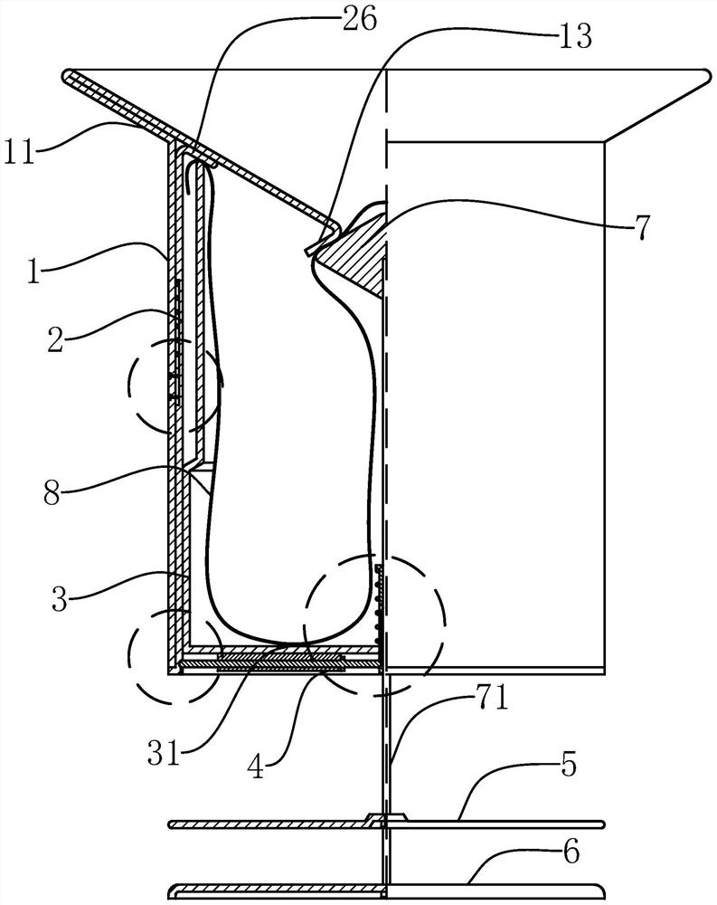
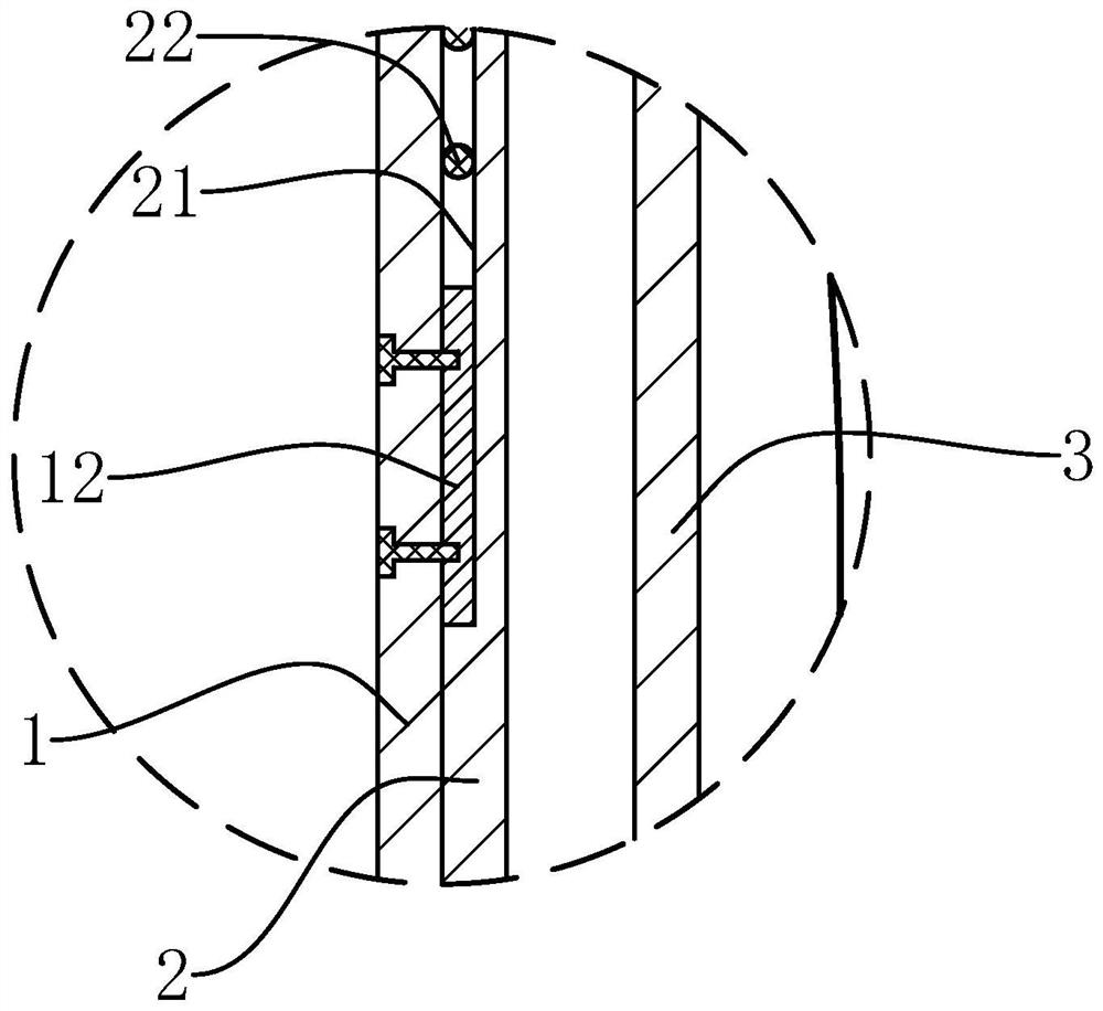
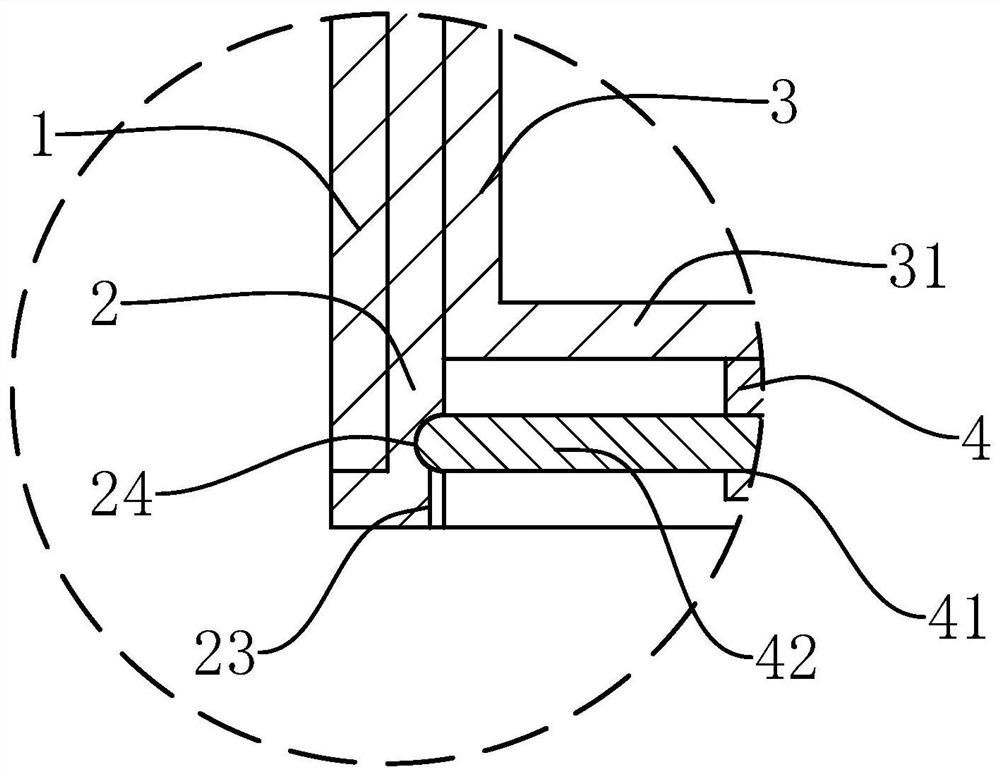
[0042] The following are specific embodiments of the present invention and in conjunction with the accompanying drawings, the technical solutions of the present invention are further described, but the present invention is not limited to these embodiments.

[0043] Such as Figure 1-6 As shown, a high-efficiency vomiting receiving device of the present invention includes an outer barrel and an inner barrel 3. The outer barrel includes a cylindrical auxiliary barrel 2 and a cylindrical main barrel 1 that fits on the outside of the auxiliary barrel 2, and also includes a trumpet-shaped structure. The top plate 11, the top plate 11 has a small end with a relatively small opening and a large end with a relatively large opening, the large end of the top plate 11 is located above the small end, the top of the main cylinder 1 is fixed coaxially with the bottom surface of the top plate 11, and the top of the main cylinder 1 is located on the top plate 11 Between the large end and the ...


PUM


Abstract

The invention provides a high-efficiency vomiting receiving device, which belongs to the field of nursing medical devices. It solves the problem of inconvenient use of the existing vomit receiving device. The high-efficiency vomiting receiving device includes an outer barrel and an inner barrel. The outer barrel includes an auxiliary barrel and a main barrel, and also includes a trumpet-shaped top plate. The top of the main barrel is fixed to the bottom of the top plate. Including the return spring, the bottom of the inner barrel is fixed with a bottom plate, the bottom plate is provided with a retaining hole, and the upper and lower pressing plates and the top are fixed with a stopper, and the bottom end is fixed with the upper pressing plate. It is put through the blocking hole, and also includes a compression spring set on the adjustment sleeve. There is a connecting hole on the upper pressing plate, and a connecting rod passing through the connecting hole. The top and bottom ends of the connecting rod are fixed with the bottom plate and the lower pressing plate. A connecting block is fixed on the rod wall of the connecting rod, and an adjusting seat is fixed on the bottom surface of the base plate. The device is not only convenient for receiving vomitus, but also can be used in daily life.

Description

technical field [0001] The invention belongs to the technical field of rehabilitation aids and nursing medical devices, and relates to a high-efficiency vomiting receiving device. Background technique [0002] The existing medical vomiting receiving device is generally an ordinary garbage can, and there are the following problems in use: 1. The operation is troublesome. First, it is necessary to open the cover or step on the pedal to open the garbage can, and then align the mouth of the garbage can and carry out the operation. Vomiting, so once you vomit immediately after opening the cover, it will cause pollution; 2. Generally, the height of the trash can is not enough, you need to lift the trash can or bend over to avoid splashing of vomit, which is very laborious; 3. Once the trash can is overturned , the vomit will pour out; 4. If you forget to close the cover, the vomit will emit odor. [0003] The existing application number is 201710052932.4, which is a Chinese inven...

Claims


Application Information

Patent Timeline
Patent Type & Authority Patents(China)
IPC IPC(8): B65F1/06B65F1/16B65F1/08
Inventor 刘洪晓李会黄坤张丽丽
Owner THE AFFILIATED HOSPITAL OF QINGDAO UNIV
Why Eureka
Try Eureka