Dryer

A dryer and unit technology, applied in dryers, drying, drying of solid materials, etc., can solve the problems of affecting drying capacity and drying efficiency, small transfer range, insufficient material supply, etc., so as to avoid affecting drying. Dry quantity and drying efficiency, avoid small transfer range, and prevent insufficient feeding effect

Pending Publication Date: 2019-05-21
ANHUI PROVINCE YINGSHANG COUNTY SANJIN GRAINS ANDOILS CO LTD
View PDF0 Cites 2 Cited by
  • Summary
  • Abstract
  • Description
  • Claims
  • Application Information

AI Technical Summary

Problems solved by technology

[0002] Dryer is a device for reducing the moisture content of objects. It is widely used in various industries. In terms of grain production, in order to achieve safe storage of grain without mildew, the moisture content of grain must be reduced to a safe moisture level for storage. The existing The drying machine can not meet people's use;
[0003] Existing dryers have certain disadvantages in use. First, when the grain particles are transferred on the conveyor belt, it is easy to cause the particles to fall from the cracks, or affect the upward transfer of hot steam, affecting the internal drying effect. Secondly, it cannot Make the hot steam generated by the drying unit transfer upwards evenly. The small transfer range will easily cause uneven drying. Finally, it is not convenient to feed the grain particles, and it is easy to cause insufficient feeding due to slipping, which will affect the drying capacity and drying efficiency. , has brought a certain impact on people's use process, for this reason, we propose a dryer

Method used


Image

  • Dryer
  • Dryer
  • Dryer

Examples


Embodiment 1

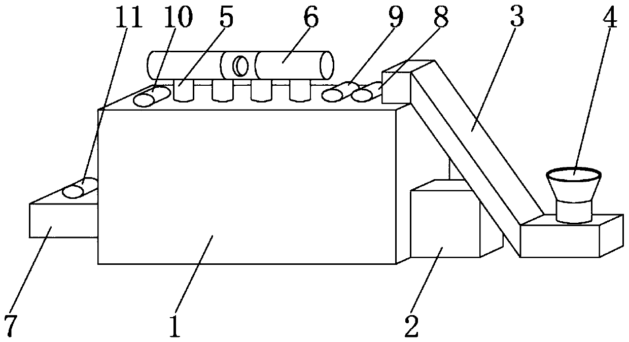
[0023] Such as Figure 1-6 As shown, a dryer includes a main body box 1 of the dryer and a drying unit 2, the drying unit 2 is composed of an evaporator, a compressor, a condenser and an expansion valve, and the main body box 1 of the dryer is surrounded by The front box board 12, the rear box board 13, the left box board 20 and the right box board 21 are composed. The drying unit 2 is fixedly installed on the bottom side of the dryer main box 1, and on the upper side of the dryer main box 1. The feeding cylinder 3 is fixedly installed, and the feeding cylinder 3 is located at the upper end of the drying unit 2, the feeding hopper 4 is fixedly installed at the bottom of one end of the feeding cylinder 3, and the upper end of the main body box 1 of the dryer is fixedly installed with four sets of air-inducing ducts 5 , the upper ends of the four groups of air-introduction ducts 5 are fixedly installed with an air collecting pipe 6, the other side of the main body box 1 of the d...

Embodiment 2

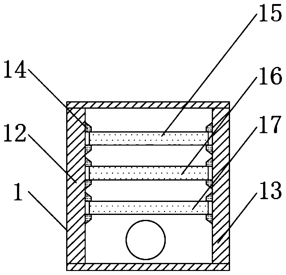
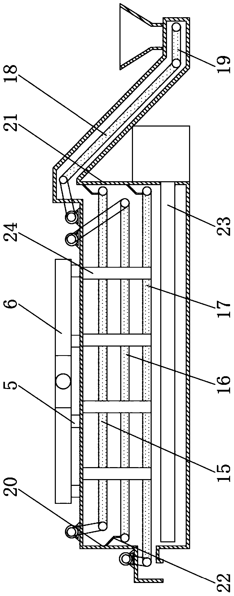
[0025] Such as Figure 1-6 As shown, one end of the No. 1 conveyor belt 15 is positioned at the lower end of the material retaining plate 22 near the right box plate 21 inwall, and the other end of the No. 1 conveyor belt 15 is 20 centimeters away from the left box panel 20. The No. 1 conveyor belt 15 and the No. 3 motor 10 Connected by a transmission belt, one end of the No. 2 conveyor belt 16 is located at the lower end of the material retaining plate 22 near the inner wall of the left caseboard 20, and the other end of the No. 2 conveyor belt 16 is 20 centimeters away from the right caseboard 21. The No. 2 conveyor belt 16 and the No. 2 motor 9 is connected by a transmission belt, one end of the No. 3 conveyor belt 17 is located at the lower end of the material baffle plate 22 on the inner wall of the right box plate 21, and the other end of the No. 3 conveyor belt 17 is located inside the discharge cylinder 7. The No. 3 conveyor belt 17 and the No. 4 motor 11 is connected ...


PUM


Abstract

The invention discloses a dryer. The dryer comprises a dryer main body box and a drying unit; the drying unit consists of an evaporator, a compressor, a condenser and an expansion valve; the peripheryof the dryer main body box consists of a front box plate, a back box plate, a left box plate and a right box plate; and the drying unit is fixedly mounted on one side of the bottom end of the dryer main body box. The dryer is provided with a support rod, a ventilation pipe, an exhaust port and a feeding cross bar; when grain particles are conveyed on a conveying belt after entering the dryer mainbody box, the particles can be prevented from falling from cracks, and meanwhile, the drying effect is improved; hot steam generated by the drying unit can be uniformly transferred up to prevent nonuniform drying caused by narrow transfer range; and the grain particles can be preferably loaded, so that the supply insufficiency caused by slippage is prevented, the influence on the drying quantityand the drying efficiency is prevented, a certain practicability is achieved, and the better application prospect is achieved.

Description

technical field [0001] The invention relates to the field of dryers, in particular to a dryer. Background technique [0002] Dryer is a device for reducing the moisture content of objects. It is widely used in various industries. In terms of grain production, in order to achieve safe storage of grain without mildew, the moisture content of grain must be reduced to a safe moisture level for storage. The existing The dryer can not meet the needs of people; [0003] Existing dryers have certain disadvantages in use. First, when the grain particles are transferred on the conveyor belt, it is easy to cause the particles to fall from the cracks, or affect the upward transfer of hot steam, affecting the internal drying effect. Secondly, it cannot Make the hot steam generated by the drying unit transfer upwards evenly. The small transfer range will easily cause uneven drying. Finally, it is not convenient to feed the grain particles, and it is easy to cause insufficient feeding due...

Claims


Application Information

Patent Timeline
Patent Type & Authority Applications(China)
IPC IPC(8): F26B17/04F26B23/10F26B25/00
Inventor 金荣珍
Owner ANHUI PROVINCE YINGSHANG COUNTY SANJIN GRAINS ANDOILS CO LTD
Why Eureka
Try Eureka