
Optical glass stress detecting system and detecting method

A stress detection and optical glass technology, applied in the field of optical detection, can solve the problems of reducing the measurement accuracy and error of phase delay, and achieve the effect of simplifying the structure, improving the accuracy and eliminating the rotation error.

Active Publication Date: 2019-05-21
SHANDONG UNIV
View PDF9 Cites 2 Cited by
  • Summary
  • Abstract
  • Description
  • Claims
  • Application Information

AI Technical Summary

Problems solved by technology

[0004] However, when the 1 / 4 wave plate method is used for testing, the components in the measurement system need to be rotated, which will bring errors during the rotation process and reduce the measurement accuracy of the phase delay.

Method used


Image

  • Optical glass stress detecting system and detecting method
  • Optical glass stress detecting system and detecting method
  • Optical glass stress detecting system and detecting method

Examples


Embodiment Construction

[0039] The technical solutions in specific embodiments of the present invention will be described in detail and completely below in conjunction with the accompanying drawings. Apparently, the described embodiments are only some specific implementations of the general technical solution of the present invention, but not all implementations. All other embodiments obtained by those skilled in the art based on the general concept of the present invention fall within the protection scope of the present invention.

[0040] In describing the present invention, it is to be understood that the terms "center", "upper", "lower", "front", "rear", "left", "right", "vertical", "horizontal", The orientations or positional relationships indicated by "top", "bottom", "inner", "outer", etc. are based on the orientations or positional relationships shown in the drawings, and are only for the convenience of describing the present invention and simplifying the description, rather than indicating o...


PUM


Abstract

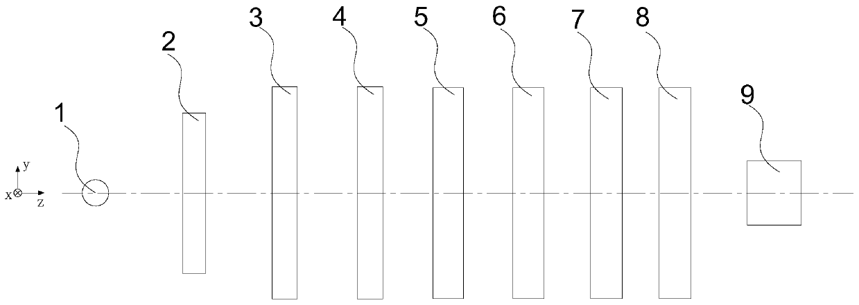
The invention provides an optical glass stress detecting system and detecting method. The optical glass stress detecting system comprises a light source being a monochromatic light source, a first linear polarized element, a variable phase delayer, a second linear polarized element, and a detection element. The polarization direction of the first linear polarized element is perpendicular to a horizontal plane. The included angle between the fast axis direction of the variable phase delayer and the horizontal plane is 45 degrees. The polarization direction of the second linear polarized elementis parallel to the horizontal plane. The first linear polarized element, the variable phase delayer, the second linear polarized element, and the detection element are arranged successively along thelight propagation direction of the light source. A to-be-detected sample is arranged between the first linear polarized element and the variable phase delayer. Therefore, the rotation error is eliminated; the measurement precision of the phase delay is improved; and thus the precision of the optical glass stress detection is enhanced. Meanwhile, the structure of the optical glass stress detectionsystem in the prior art is simplified; the requirement on the optical element is reduced; and thus the cost is lowered.

Description

technical field [0001] The invention belongs to the field of optical detection, in particular to an optical glass stress detection system and detection method. Background technique [0002] In the production process of optical glass, due to material reasons or production processes, the glass structure will be deformed, resulting in birefringence under the action of stress, that is, stress birefringence. Therefore, by detecting the amount of phase retardation due to birefringence, the stress of the optical glass can be detected. [0003] In the prior art, a 1 / 4 wave plate method is usually used to detect the phase retardation of glass. Reference attached figure 1 , the measurement system includes a polarizer 1', a sample to be tested 2', a 1 / 4 wave plate 3' and a polarizer 4'. The light from the light source first passes through the polarizer to become linearly polarized light, then passes through the sample to be tested and becomes elliptically polarized light, and then p...

Claims


Application Information

Patent Timeline
Patent Type & Authority Applications(China)
IPC IPC(8): G01L1/24
Inventor 魏志伟刘维新赵文谦丁星卜马龙行
Owner SHANDONG UNIV
Learn More