Novel power distribution network disconnecting knife switch

A technology for isolating knife switches and distribution networks, applied in the direction of electrical components, air switch components, etc., can solve the problems of small operating ring, poor contact, and poor contact of the isolating knife switch, so as to avoid heat generation or even damage, increase The contact area and the effect of sharing the pressure of the knife switch

Pending Publication Date: 2019-05-21
STATE GRID CORP OF CHINA +1
View PDF0 Cites 2 Cited by
  • Summary
  • Abstract
  • Description
  • Claims
  • Application Information

AI Technical Summary

Problems solved by technology

However, the existing knife switches have the following common defects: First, the contact area at the static and dynamic contacts of the isolated knife switch is too small, which can easily cause heat and then cause failures, resulting in circuit tripping
The second is that the operating ring of the isolation knife switch is too small, and the operating rod should not be placed in the operating ring when operating under the rod, which greatly reduces the operating efficiency
There are even operators who directly use the operating rod to push the edge of the isolation knife to operate, which can easily cause the isolation knife to be wrong, resulting in poor contact and failure caused by heat.
The third is the wear and tear caused by multiple opening and closing of the rotating shaft of the isolation knife, the corrosion caused by long-term operation, etc., resulting in poor contact and excessive contact resistance, which will cause the equipment to heat up and burn out in severe cases

Method used


Image

  • Novel power distribution network disconnecting knife switch
  • Novel power distribution network disconnecting knife switch
  • Novel power distribution network disconnecting knife switch

Examples


Embodiment Construction

[0022] The technical solutions of the present invention will be described in further detail below through specific implementation methods.

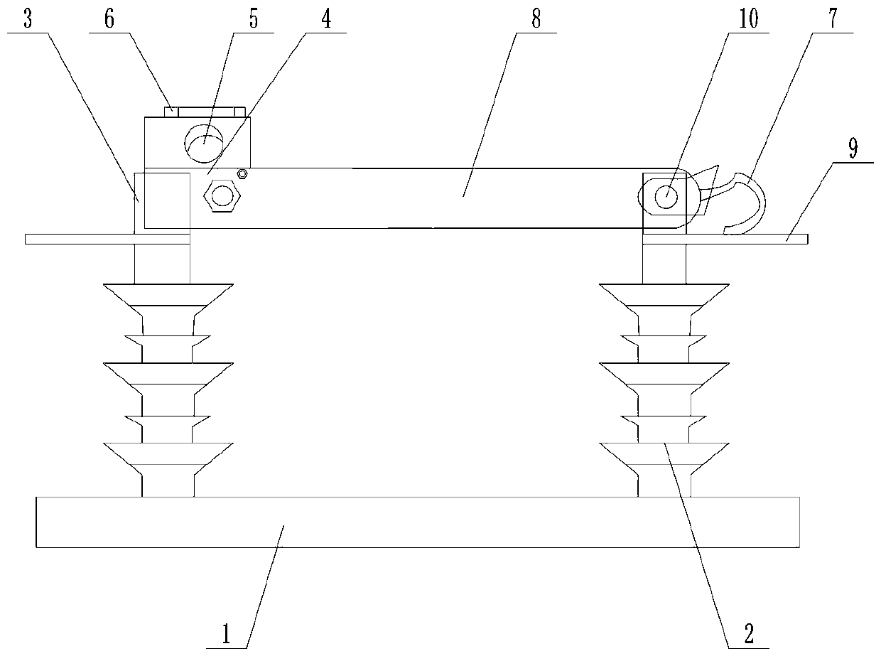
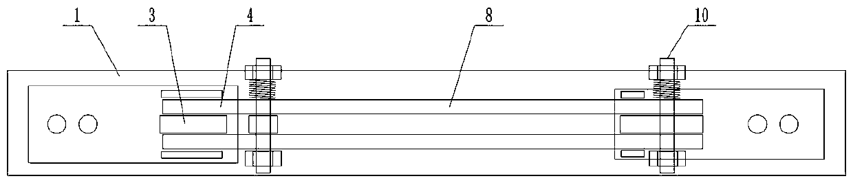
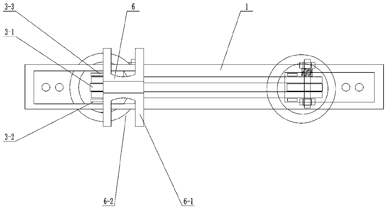
[0023] Such as Figure 1-Figure 5 As shown, a new type of distribution network isolation switch includes a base 1, an insulator 2, a switch knife 8, a static contact 3, a moving contact 4 and an operating ring 5, and the moving contact 4 is located at the free end of the switch knife 8. Limiting devices 6 are arranged on the left and right sides below the operating ring 5, and the limiting devices 6 include a horizontal limiting plate 6-1 and a U-shaped groove 6-2 opened on the horizontal limiting plate. A reflective coating is arranged below the horizontal limiting plate 6-1. The opening direction of the U-shaped groove is outward or forward or backward, and the orientation of the opening direction of the U-shaped groove is determined according to the actual working environment. The opening of the U-shaped groove is larger than the size...


PUM


Abstract

The invention provides a novel power distribution network disconnecting knife switch. The novel power distribution network disconnecting knife switch comprises a base, an insulator, a static contact,a movable contact, a knife switch and an operating ring; limiting devices are arranged on the left side and the right side of the lower portion of the operating ring; the limiting device comprises a horizontal limiting plate and at least one U-shaped groove formed in the horizontal limiting plate; and a reflective coating layer is arranged below the horizontal limiting plate. The static contact comprises a main pile head and auxiliary pile heads arranged on the two sides of the main pile head. A copper braided belt is arranged at the rotating shaft of the movable contact. The novel power distribution network disconnecting switch has the advantages that the operation loop is easier to operate, the heating probability is smaller, and the problem of heating caused by the increase of the corrosion resistance of the knife brake is overcome.

Description

technical field [0001] The invention relates to a novel distribution network isolation switch. Background technique [0002] The distribution network isolation switch is one of the commonly used power equipment in the distribution network. Its main feature is that it has no arc extinguishing ability, and can only open and close the circuit when there is no load current. Its main function is: after opening, establish a reliable insulation gap, and isolate the equipment or lines that need to be repaired from the power supply with an obvious disconnection point to ensure the safety of maintenance personnel and equipment; ;Small current in the split line, such as bushing, busbar, short cable, no-load transformer with a certain capacity and other equipment. [0003] At present, the use of isolation switch in the distribution network is very common. However, the existing knife switch has the following common defects: First, the contact area at the dynamic and static contacts of ...

Claims


Application Information

Patent Timeline
Patent Type & Authority Applications(China)
IPC IPC(8): H01H31/02H01H21/54H01H21/02
Inventor 林德山张云鹏魏继承王建华周保民梅卫东姜祖明伏虎姚竟成严建邦刘欣阳刘蓉吕玲杨长青李峰刘承惠程嵩刘煜
Owner STATE GRID CORP OF CHINA
Why Eureka
Try Eureka