Hinge device for appliances with top loading

A component and device technology, applied in the field of household equipment, can solve problems such as collisions, high-speed emergency stops, and large accidents

Inactive Publication Date: 2019-05-21
C M I CERNIERE MECCANICHE IND
View PDF7 Cites 0 Cited by
  • Summary
  • Abstract
  • Description
  • Claims
  • Application Information

AI Technical Summary

Problems solved by technology

[0005] Disadvantages of such known hinge devices include that they do not allow the door to be in a half-open position, they are only stable when the door is fully open or closed
[0006] Another disadvantage of said known devices consists in the fact that they allow considerable weight to counterbalance the weight of the door, so that although only a little force is required to open the door, since the movable part of the device is fixed to the door of the device, the The acti...

Method used


Image

  • Hinge device for appliances with top loading
  • Hinge device for appliances with top loading
  • Hinge device for appliances with top loading

Examples


Embodiment Construction

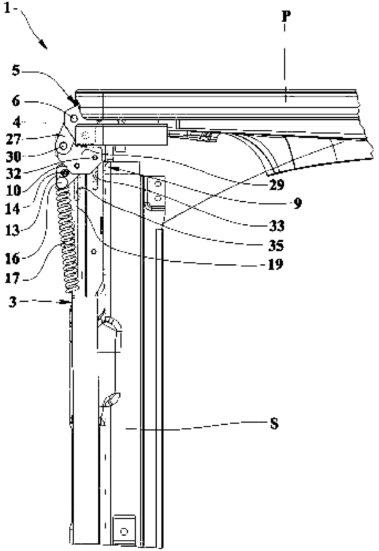
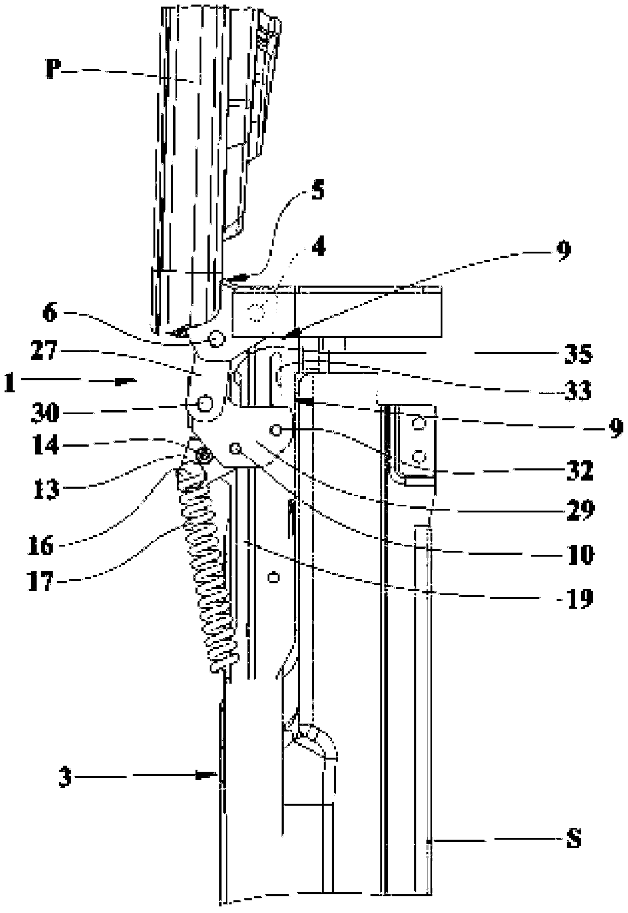
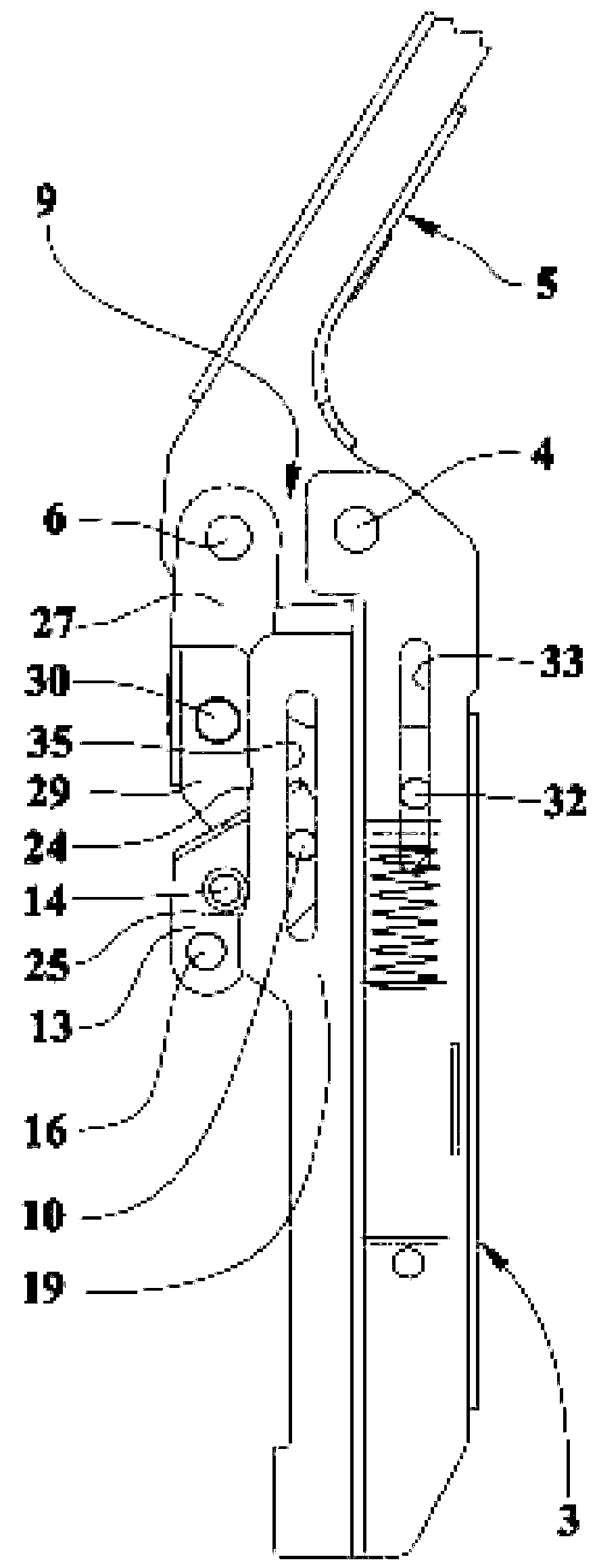
[0022] refer to figure 1 -15, number 1 refers to the hinge device for top-loading household appliances, which is the subject of this application.

[0023] The hinge device for a top-loading household appliance is equipped with a first fixing part 3 configured to be fixed to a body S, a frame or structure of a household appliance such as a top-loading dryer. The first fixed part 3 is rotatably connected to the second fixed part 5 through the hinge pin 4, and the second fixed part 5 is configured to be fixed on the upper door P or the opening of the household appliance to allow the door to be fully opened and closed. The opening and closing swing, and vice versa for the corresponding opening of the door of the household appliance.

[0024] The axis of rotation of said hinge pin 4 is horizontal or nearly horizontal in an operating situation of the household appliance, and the geometric plane defined by said door in the closed condition is horizontal or nearly horizontal. Herein...


PUM


Abstract

A hinge device for appliances with top loading has a first fixing means (3) assigned to be fixed to a body (S) or framework of an appliance and pivotally connected, by means of a hinge pin (4), to a second fixing means (5) assigned to be fixed to a top door (P) or hatch of the appliance to allow the opening and closing strokes between extreme opening and closing conditions of said door. In an operative condition, the rotation axis of said hinge pin (4) and the plane of the door in the closed condition are horizontal or almost horizontal. The second fixing means (5) is provided with a first connection pin (6) parallel to and spaced from the hinge pin (4),said first connection pin (6) is connected to an end of a transmission means (9) whose opposite end has a second connection pin (10) parallel to the first connection pin (6) and which can slide in a second slot means (35) of a shaped guide means (19) of the first fixing means (3) and nearly rectilinear and parallel to the path portion (21).Such second connection pin (10) is connected to a shaped body means (13) comprising at least a roll means (14) and a coupling means (16) for and end of a resilient means (17) acting at least in adirection according to the opening direction. Said shaped guide means (19) has a path portion (21) delimited between a first extremity (22) and a second extremity (23) thereof (21) and having at leasta recess means (24) placed between said extremities (22, 23) where the roll means (14) abuts with said path portion (21) and moves along it in the opening stroke starting from the closed condition, in which the roll means (14) abuts the first extremity (22). The roll means(14) reaches at least a metastable opening condition where it (14) is in the at least one recess means (24) and it (14) abutswith one edge of said recess means (24) facing the second extremity (23) until, due to a thrust towards the opening direction sufficient to leave the recess means (24), the roll means(14) reaches thecondition of extreme opening in which it (14) abuts against the second extremity (23) and vice versa in the closing stroke.

Description

technical field [0001] This application relates to the field of household appliances and furniture, and relates to hinge devices for top loading or top entry appliances, especially for household appliances such as clothes dryers, washing machines, box refrigerators and the like which are equipped with horizontal pivots The door and the door is configured horizontally to close the case. [0002] With respect to the situation from closed to fully open of the hinge device, the hinge device is configured to allow the door to rotate or swing open and close, respectively, and vice versa, so that the rotation from closed to fully open is preferably within Between 86°-90°, but can be smaller or larger. Background technique [0003] The word "stroke" mentioned hereafter in this document, such as opening swing and closing swing, refers to the rotation or movement of the parts of the hinge device around the rotating needle of the device, or refers to the door fixed to the part. Or th...

Claims


Application Information

Patent Timeline
IPC IPC(8): E05F1/10E05F1/12
CPCE05F1/1066E05F1/1269E05Y2201/21E05Y2201/264E05Y2800/75E05Y2900/30E05Y2900/31E05Y2900/312
Inventor 艾罗司·葛拉迪
Owner C M I CERNIERE MECCANICHE IND
Why Eureka
Try Eureka