Method and device for the functional testing of a fibre-optic sensor and computer program product

A fiber optic sensor and functional testing technology, which is applied in the direction of using optical devices to transmit sensing components, mechanical equipment, and measurement of the force of changes in optical properties of materials when they are stressed, and can solve the problem of determining the wrong state of measurement signal technology facilities, etc. question

Inactive Publication Date: 2019-05-21
FOS4X
View PDF7 Cites 5 Cited by
  • Summary
  • Abstract
  • Description
  • Claims
  • Application Information

AI Technical Summary

Problems solved by technology

Deviations in the measurement signal can lead to incorrect status determinations of technical installations, for example due to faulty fiber optic sensors

Method used


Image

  • Method and device for the functional testing of a fibre-optic sensor and computer program product
  • Method and device for the functional testing of a fibre-optic sensor and computer program product
  • Method and device for the functional testing of a fibre-optic sensor and computer program product

Examples


Embodiment Construction

[0016] In the following text, unless stated otherwise, the same reference signs are used for the same elements and the same active elements.

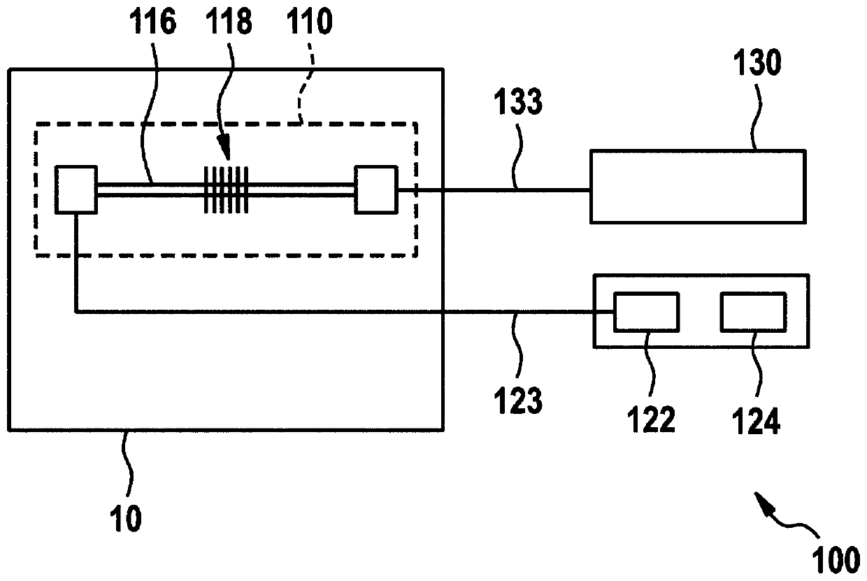
[0017] Figure 1A A schematic diagram of a device 100 for functional testing of an optical fiber sensor 110 according to an embodiment of the present disclosure is shown. Therefore, the fiber optic sensor 110 is shown by way of example only. Other types of fiber optic sensors may be used with embodiments of the present disclosure.

[0018] The device 100 comprises: a receiving unit 122 for receiving an optical sensor signal output by the fiber optic sensor 110 ; and an evaluation unit 124 . The evaluation unit 124 is configured to determine the first variable according to the optical sensor signal; determine whether the first variable is within a predetermined range; if the first variable is outside the predetermined range, then determine the failure of the fiber optic sensor 110; if it is determined that the first variable is within t...


PUM


Abstract

The invention relates to a method (200) for the functional testing of a fibre-optic sensor (110). The method (200) comprises receiving (220) optical sensor signals of the fibre-optic sensor (110) in an evaluation unit (124), determining (230) a first variable from the optical sensor signals, determining (240) whether the first variable lies within a pre-determined range, determining (250) a malfunction of the fibre-optic sensor (110) if the first variable lies outside the pre-determined range, and determining (260) a second variable from the optical sensor signals, which is different from thefirst variable, if it is determined that the first variable lies within the pre-determined range, the second variable declaring a parameter that is to be determined by the fibre-optic sensor (110).

Description

[0001] The present disclosure relates to a method and apparatus for functional testing of fiber optic sensors and to a computer program product. In particular, the present disclosure relates to determining deficiencies in measurement systems using fiber optic sensors. Background technique [0002] Fiber optic sensors can be used to monitor technical installations. Fiber optic sensors provide measurement signals which can indicate, for example, the state of a technical system. For example, a deviation of the measurement signal due to a fault in the fiber optic sensor can lead to an incorrect status determination of the technical installation. [0003] Therefore, it is necessary to provide a method and device for functional testing of optical fiber sensors. Contents of the invention [0004] The object of the present disclosure is to specify a method and a device and a computer program product for functional testing of fiber optic sensors, which are able to detect failures o...

Claims


Application Information

Patent Timeline
Patent Type & Authority Applications(China)
IPC IPC(8): G01D18/00G01H9/00G01L1/24G01P15/093G01P21/00G01D5/353
CPCG01P21/00G01L1/24G01H9/004F05B2270/804F03D17/00G01P15/093G01D5/353G01D18/00Y02E10/72
Inventor 马蒂亚斯·穆勒
Owner FOS4X
Why Eureka
Try Eureka