Split type mold for hollow sphere precise manufacturing

A split, hollow ball technology, applied in the field of injection molding, can solve problems such as increased sales costs and inability to use

Pending Publication Date: 2019-05-24
泰州市姜堰区银星冲压制品厂
View PDF0 Cites 0 Cited by
  • Summary
  • Abstract
  • Description
  • Claims
  • Application Information

AI Technical Summary

Problems solved by technology

The above two production methods have limitations in use, and cannot perfectly provide hollow balls of various diameters and sizes, so they cannot fully meet the needs of customers, and are prone to the following problems: 1. The balls synthesized by two semicircles are waste. It takes time to increase the cost of sales; 2. The ball made of pipe has space at both ends. If the demand cannot have double-ended holes, the ball cannot be used

Method used


Image

  • Split type mold for hollow sphere precise manufacturing

Examples


Embodiment 1

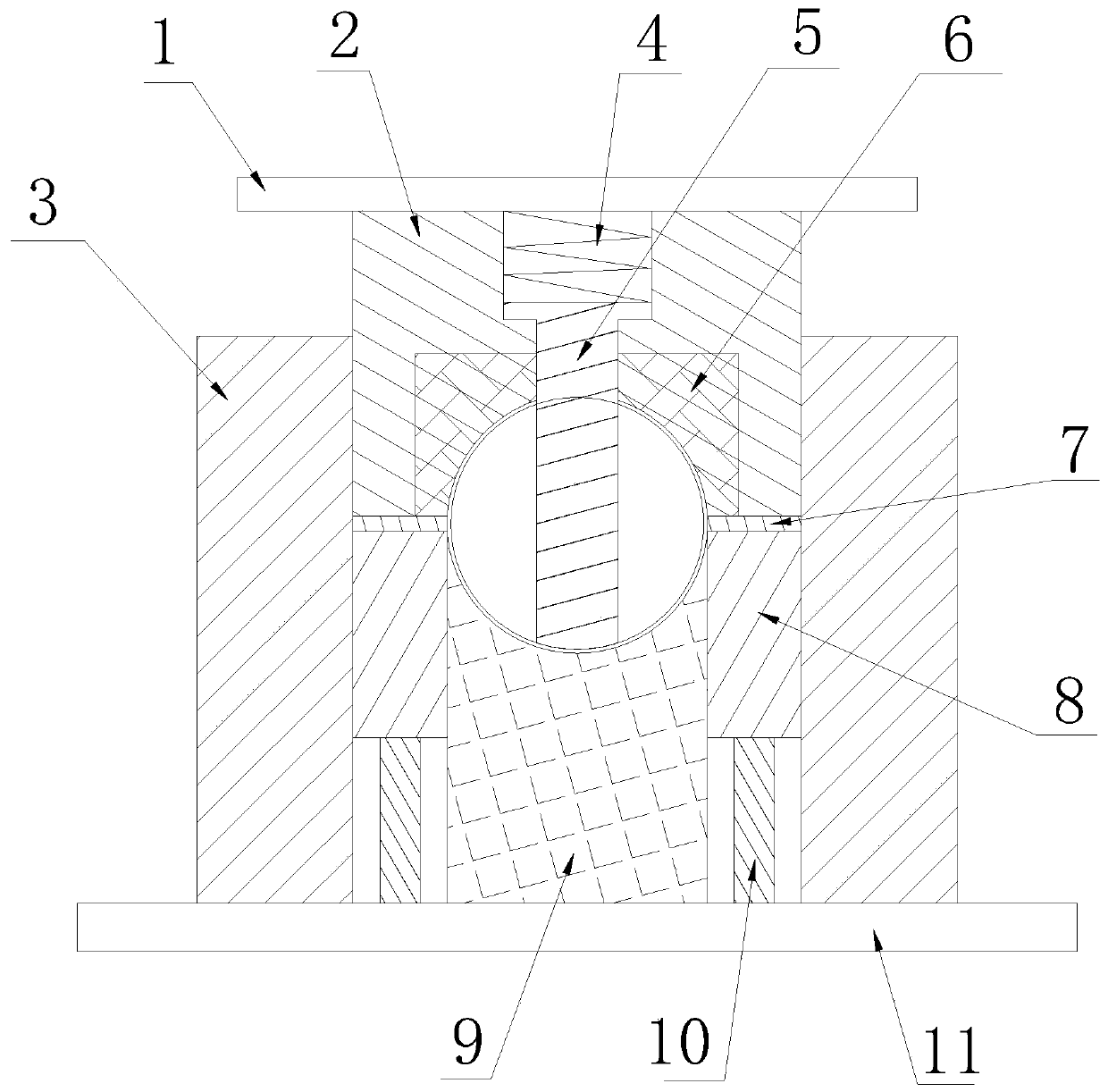
[0018] To make a hollow ball with a diameter of 50 cm, first, the upper mold 2, the compression spring 4, the upper mold inner ejector rod 5 and the upper mold inner phase block 6 are retracted to the upper point, and secondly, the lower cylinder pushes the ejector rod 10 to the guide ring 8 and The telescopic piece 7 reaches the mouth edge taper of the outer guide mold 3, and then puts the semi-finished product into the lower mold 9, and then the upper mold 2 goes down to the position of 25 cm from the center of the ball, and then the upper mold 2 returns, and the ejector rod 10 is compressed. Under the action of the spring 4, the bottom surface of the ball is pressed to prevent the ball from sticking to the cavity of the upper mold 2. Next, the lower cylinder pushes the ejector rod 10 again so that the guide ring 8 and the telescopic piece 7 rise to the taper of the mouth of the outer guide mold 3. Return to the original state, because the telescopic sheet 7 is quartered and ...

Embodiment 2

[0020] To make a hollow ball with a diameter of 80cm, firstly, the upper mold 2, the compression spring 4, the upper mold inner ejector rod 5 and the upper mold inner phase block 6 are retracted to the upper point, and secondly, the lower cylinder pushes the ejector rod 10 to the guide ring 8 and The telescopic piece 7 reaches the mouth edge taper of the outer guide mold 3, then puts the semi-finished product into the lower mold 9, and then the upper mold 2 goes down to the position of 40 cm from the center of the ball, then the upper mold 2 returns, and the ejector rod 10 is compressed Under the action of the spring 4, the bottom surface of the ball is pressed to prevent the ball from sticking to the cavity of the upper mold 2. Next, the lower cylinder pushes the ejector rod 10 again so that the guide ring 8 and the telescopic piece 7 rise to the taper of the mouth of the outer guide mold 3. Return to the original state, because the telescopic sheet 7 is quartered and evenly s...

Embodiment 3

[0022] To make a hollow ball with a diameter of 90 cm, first, the upper mold 2, the compression spring 4, the upper mold inner ejector rod 5 and the upper mold inner phase block 6 are retracted to the upper point, and secondly, the lower cylinder pushes the ejector rod 10 to the guide ring 8 and The telescopic piece 7 reaches the mouth edge taper of the outer guide mold 3, then puts the semi-finished product into the lower mold 9, and then the upper mold 2 goes down to the position of 45 cm from the center of the ball, then the upper mold 2 returns, and the ejector rod 10 is compressed Under the action of the spring 4, the bottom surface of the ball is pressed to prevent the ball from sticking to the cavity of the upper mold 2. Next, the lower cylinder pushes the ejector rod 10 again so that the guide ring 8 and the telescopic piece 7 rise to the taper of the mouth of the outer guide mold 3. Return to the original state, because the telescopic sheet 7 is quartered and evenly sp...


PUM


Abstract

The invention discloses a split type mold for hollow sphere precise manufacturing. The mold comprises an upper bottom plate and a lower bottom plate, upper molds are arranged on the two sides of the bottom of the upper bottom plate, the two outer sides of the upper molds are attached to an outer guide mold, a compression spring is arranged between the upper molds, the bottom of the compression spring is connected with an upper mold inner material returning rod, upper mold inner phase blocks are arranged on the two sides of the upper mold inner material returning rod, telescopic pieces are tightly attached to the bottoms of the upper mold inner phase blocks, guide rings are arranged at the bottoms of the telescopic pieces, a lower mold is arranged between the guide rings, ejector rods are arranged on the bottom of the guide rings, and a lower bottom plate is arranged on the bottoms of the ejector rods. A made hollow sphere is free of welding, saves time and materials, is simple in structure, small in round degree and small in single hole.

Description

technical field [0001] The invention belongs to the technical field of injection molding, and in particular relates to a split mold precisely produced by hollow balls. Background technique [0002] At present, the hollow balls commonly used in the market include aluminum balls, stainless steel balls and carbon steel balls. It is to make a tube ball with a hollow tube, but there are spaces at both ends. The above two production methods have limitations in use, and cannot perfectly provide hollow balls of various diameters and sizes, so they cannot fully meet the needs of customers, and are prone to the following problems: 1. The balls synthesized by two semicircles are waste. It takes time to increase the cost of sales; 2. The ball made of the pipe has holes at both ends. If the demand cannot have double-ended holes, the ball cannot be used. In order to solve the above problems, a mold capable of producing integrally stretched hollow balls is needed. The hollow balls produc...

Claims


Application Information

Patent Timeline
IPC IPC(8): B29C45/26B22D17/22
Inventor 徐浩锁燕南季国庆
Owner 泰州市姜堰区银星冲压制品厂
Why Eureka
Try Eureka