
Underwater engineering conveying belt

An underwater engineering, conveyor belt technology, applied in the direction of conveyors, conveyor objects, transportation and packaging, etc., can solve problems such as the inability to work or rest underwater permanently, the traction motor has not been proposed or introduced, and cannot be

Inactive Publication Date: 2019-05-24
CHINA JILIANG UNIV
View PDF7 Cites 0 Cited by
  • Summary
  • Abstract
  • Description
  • Claims
  • Application Information

AI Technical Summary

Problems solved by technology

[0006] Obviously: all the above-mentioned waterproof and sealing technical measures (mainly undertaken by adopting physical sealing elements) cannot achieve effective and permanent sealing effects from the molecular level; it is not difficult to imagine: any design using such effects The underwater driving motor required for underwater engineering must not continue to work or rest underwater permanently, and must be hoisted ashore regularly for disassembly and maintenance (not maintenance) with the main task of eliminating water seepage; If you want to use an underwater drag motor with tens of thousands of watts or even millions of watts, the troubles caused by "regular disassembly to eliminate water seepage maintenance" (not counting the influence of diving depth for the time being) during its use, It is even more unimaginable, so that people dare not think of using high-power underwater drag motors in permanent underwater projects or permanent underwater appliances.
[0007] For this reason: at present, the drag motor that can be used for submersible equipment as described in the title of the present invention has not yet proposed or come out.

Method used


Image

  • Underwater engineering conveying belt
  • Underwater engineering conveying belt

Examples


Embodiment Construction

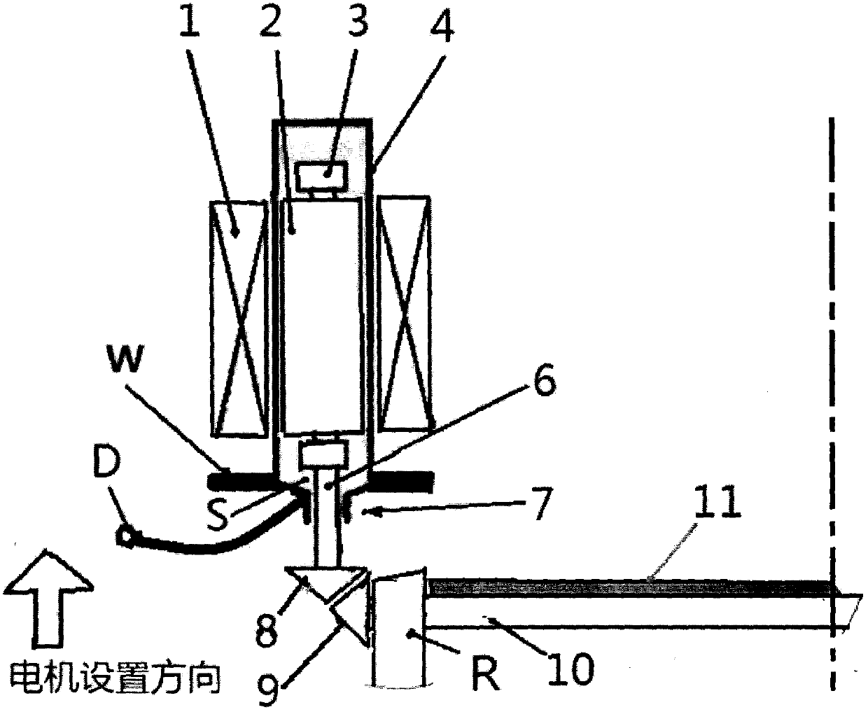
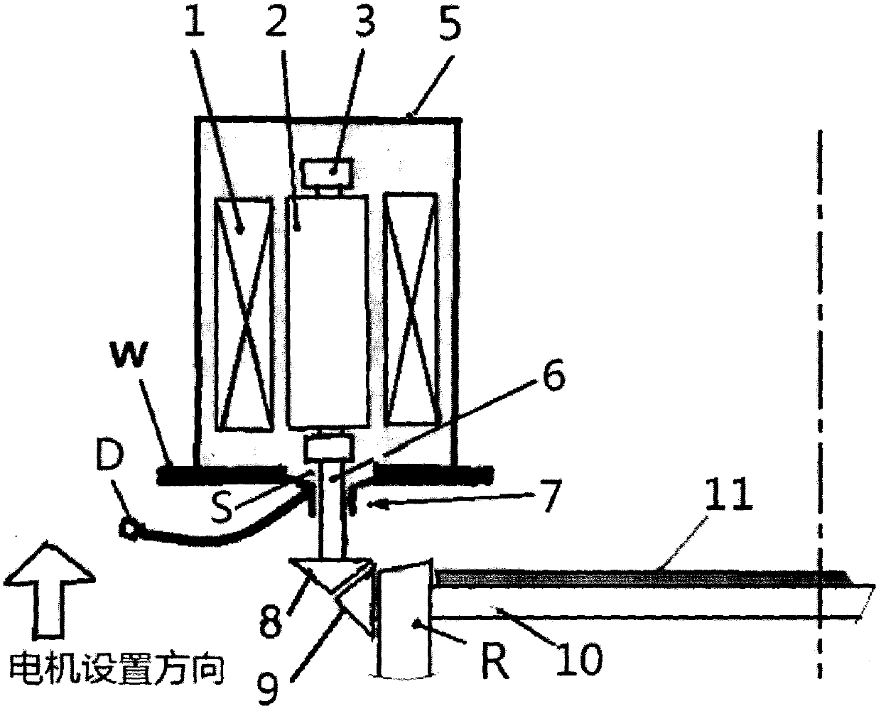
[0024] The present invention is composed of a conveyor belt structure with a support R suitable for being set underwater and a special underwater drag motor:

[0025] 1. Vertical drive (special requirements for underwater drag motors) The horizontal operation of the underwater conveyor belt 11:

[0026] The vertical helical gear 8 connected to the lower end of the vertical rotating shaft 6 and the horizontally rotating end transverse helical gear 9 connected with the horizontal roller 10 driving the horizontal conveyor belt 11 to move forward are driven as a reversing mode of mutual vertical tooth connection.

[0027] 2. The structure of an under-water drag motor:

[0028] Including: a drive motor composed of a rotor 2 and a stator 1 with embedded windings in a conventional structure to implement torque output through its shaft 6;

[0029] Its characteristics are:

[0030] At least let the rotor 2 or the rotor 2 and the stator 1 be surrounded by a narrow metal sealing isolation shield 4 ...


PUM


Abstract

The invention discloses an underwater engineering conveying belt and particularly relates to a maintenance-free (in terms of the lifetime of the conveying belt) underwater conveying belt capable of diving deeply (the water depth can exceed one thousand meters). The conveying belt is composed of an underwater conveying belt structure and a special underwater dragging motor. Firstly, the underwaterdragging motor vertically drives an underwater conveying belt (11) to horizontally operate, and driving is achieved in a gearbox mutual perpendicular toothing connection reversing mode; and secondly,according to the structure of the underwater dragging motor, at least a rotor (2) is wrapped with a metal seal isolating shielding cavity in a vertical mode, and in addition, a rotary shaft (6) capable of penetrating through a motor shaft seal (7) downwards and a filling nozzle (D) arranged directly or through a pipe coupling are arranged at the bottom of the metal seal isolating shielding cavity.All spicing gaps related to the metal seal isolating shielding cavity are connected through a detachable welding technology. According to the underwater engineering conveying belt, the aggregated duration for one-time underwater working and idling of the conveying belt can generally reach up to more than 15 years or even reach up to 50 years or more.

Description

Technical field [0001] The invention relates to an underwater mining engineering conveyor belt capable of deep diving and maintenance-free. Background technique [0002] At present, diving equipment with different specifications and models emerges endlessly. Among them, the most widely used and mature electric power equipment can only be used with various equipment that runs in the air, but cannot be used with various devices that run underwater. The main reasons are: [0003] If the motor can work underwater, it is necessary to set up a waterproof sealing structure (for example: various specifications of sealing rings made of flexible polymer materials such as rubber or plastic as the main body) to resist external water or high-pressure water to the motor Internal infiltration (Once the water body contacts the rotating motor rotor, it will cause damage to the motor). However, the setting of the waterproof sealing structure cannot resist the molecular weight of the fluid including...

Claims


Application Information

Patent Timeline
Patent Type & Authority Applications(China)
IPC IPC(8): B65G15/30B65G39/09
Inventor 梁嘉麟
Owner CHINA JILIANG UNIV
Learn More