A pipe threading device for steel cage

A technology of pipe threading device and steel cage, which is applied in construction, infrastructure engineering, sheet pile wall, etc., can solve the problem of low efficiency of manual pipe threading, save time and labor for pipe threading, prevent collision damage, and realize dismantling. The effect of convenience

Active Publication Date: 2020-11-17
国网山东省电力公司建设公司 +2
View PDF2 Cites 0 Cited by
  • Summary
  • Abstract
  • Description
  • Claims
  • Application Information

AI Technical Summary

Problems solved by technology

[0004] The present invention aims at the above-mentioned deficiencies existing in the prior art, and provides a pipe threading device for steel cages, through which a plurality of grouting pipes or acoustic measuring pipes can be clamped at one time through the clamping device, The other end realizes automatic pulling of pipes, and realizes automatic pipe threading of multiple pipes at one time under the premise of smooth pipe threading, which solves the problem of low efficiency of manual pipe threading at present, saves time and labor for pipe threading, and reduces cost

Method used


Image

  • A pipe threading device for steel cage
  • A pipe threading device for steel cage
  • A pipe threading device for steel cage

Examples


Embodiment 1

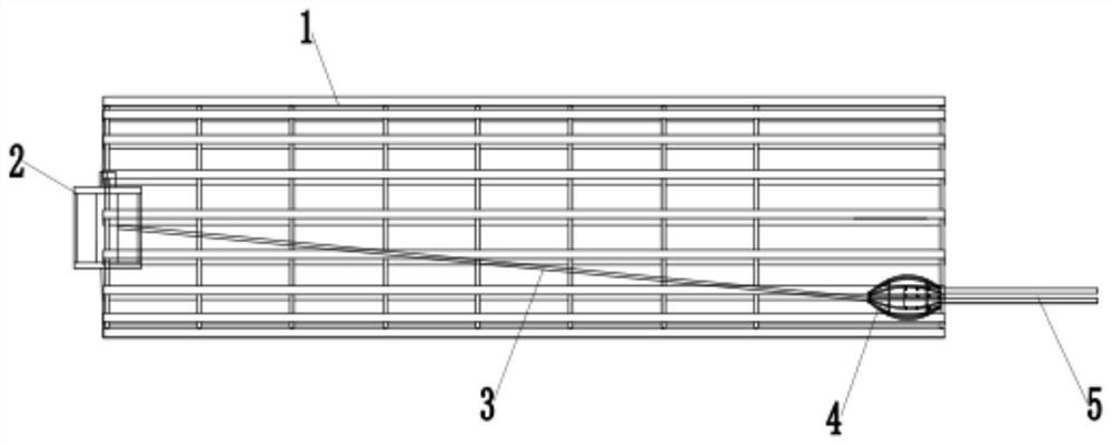
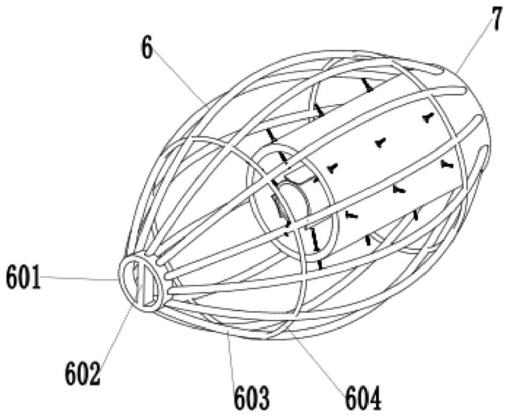
[0032] Such as figure 1 As shown, a pipe threading device for a reinforcement cage includes a guide 4 and a wire take-up device 2 connected to one end of the reinforcement cage 1, and the wire take-up device 2 passes a traction rope 3 Connect with bootstrap 4 like figure 2 As shown, the guide 4 includes a support frame 6 and a clamping device 7. The outer diameter of the support frame 6 gradually increases from both ends to the middle, and one end of the support frame 6 is connected with the traction rope 3, and the support frame 6 The other end is connected with a clamping device 7 , and the clamping device 7 is arranged in the support frame 6 .

[0033] Such as figure 1 As shown, a plurality of pipes are clamped and fixed at the same time by the clamping device 7, the staff pulls the end of the traction rope and connects it with the guider, and pulls the pipes by winding the traction rope 3 through the wire take-up device 2. Under the premise of the pipe, the automatic p...

Embodiment 2

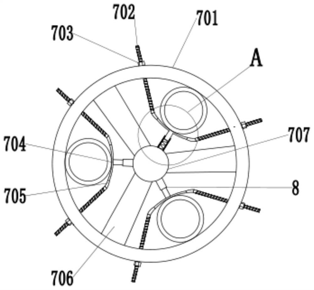
[0042] In order to increase the convenience of installing the pipe into the guide, such as image 3 , 4 As shown, the middle part of the clamp tube 701 is provided with a mounting column 707, the side wall of the mounting column 707 is connected to the inner wall of the clamp tube 701 through a connecting rod 706, and the mounting column 707 is connected to the pressure tube arc plate 704 A puller device 8 is provided between them.

[0043] The puller device 8 includes a puller 801, a spring 802, and a pull rod 803. One end of the puller 801 is connected to the mounting column 707, and the other end of the puller 801 is set on the puller 803. The puller 801 is provided with Spring 802, one end of the spring 802 is connected to the mounting column 707, the other end of the spring 802 is connected to the pull rod 803, and the end of the pull rod 803 away from the spring 802 is connected to the pressure tube arc plate 704, the pull plate device 8 is simple in structure and low i...


PUM


Abstract

The invention discloses a steel-cage pipe piecing device. The steel-cage pipe piecing device comprises a guide and a take-up device, the take-up device is connected with one end of a steel cage and isconnected with the guide through a pulling rope, the guide includes a support skeleton and a pipe clamping device, the outer diameter of the support skeleton gradually increases from two ends to themiddle, one end of the support skeleton is connected with the pulling rope while other end of the same is connected with the pipe clamping device, and the pipe clamping device is arranged in the support skeleton. Multiple grouting pipes or acoustic measuring pipes can be clamped at one time through the pipe clamping device, pipes can be automatically pulled at the other end of the steel cage by the take-up device, automatic pipe piecing for multiple pipes at one time is realized under the premise of satisfying the smooth pipe piecing, the problem of low efficiency of manual pipe piecing at present is solved, time and labor for pipe piecing are saved, and cost is reduced.

Description

technical field [0001] The invention relates to the technical field of pipe threading tools for steel cages, in particular to a pipe threading device for steel cages. Background technique [0002] The reinforcement cage refers to the steel skeleton of the pile foundation, which is used for foundation engineering. Cylindrical steel frame, the steel bars are evenly distributed, and the ring stirrups are evenly wound around the frame. During the construction of reinforced concrete piles, after the reinforcement cage is arranged, it is necessary to pass the grouting pipe and the acoustic measuring pipe through the reinforcement cage. [0003] At present, the pipe threading construction of the steel cage is generally directly operated manually. In order to prevent the end of the pipe from colliding with the ring stirrup during the pipe threading process, a guide is generally placed on the end of the pipe to avoid There is a problem that the pipe cannot be threaded due to collis...

Claims


Application Information

Patent Timeline
Patent Type & Authority Patents(China)
IPC IPC(8): E02D5/34
Inventor 刘红涛王延鹏肖鹏曹东明黄永奇刘忠声陈永辉姬晟翔邵潇菡李本浩
Owner 国网山东省电力公司建设公司
Why Eureka
Try Eureka