Double-V-shaped hybrid permanent magnet adjustable flux memory motor
A hybrid permanent magnet and memory motor technology, applied in synchronous motors with static armatures and rotating magnets, magnetic circuit rotating parts, magnetic circuit shape/style/structure, etc. The problem of large pulse, etc., can overcome the large demagnetization current pulse, reduce the amplitude, increase the power density and overload operation ability.
- Summary
- Abstract
- Description
- Claims
- Application Information
AI Technical Summary
Problems solved by technology
Method used
Image
Examples
specific Embodiment approach 1
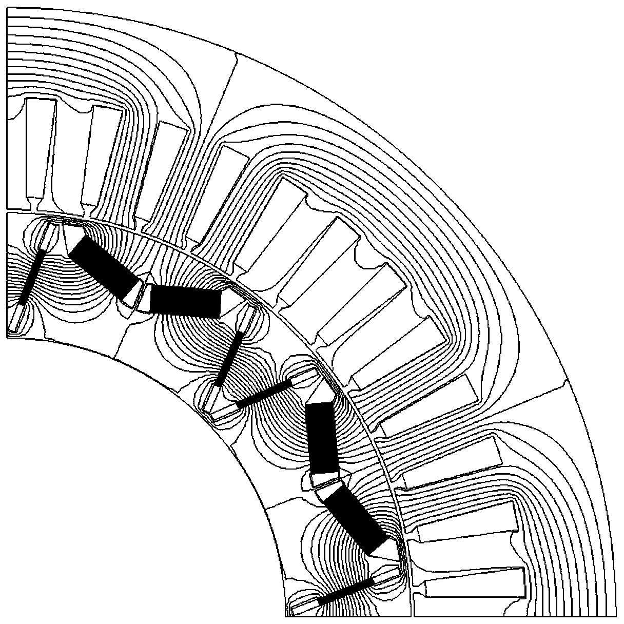
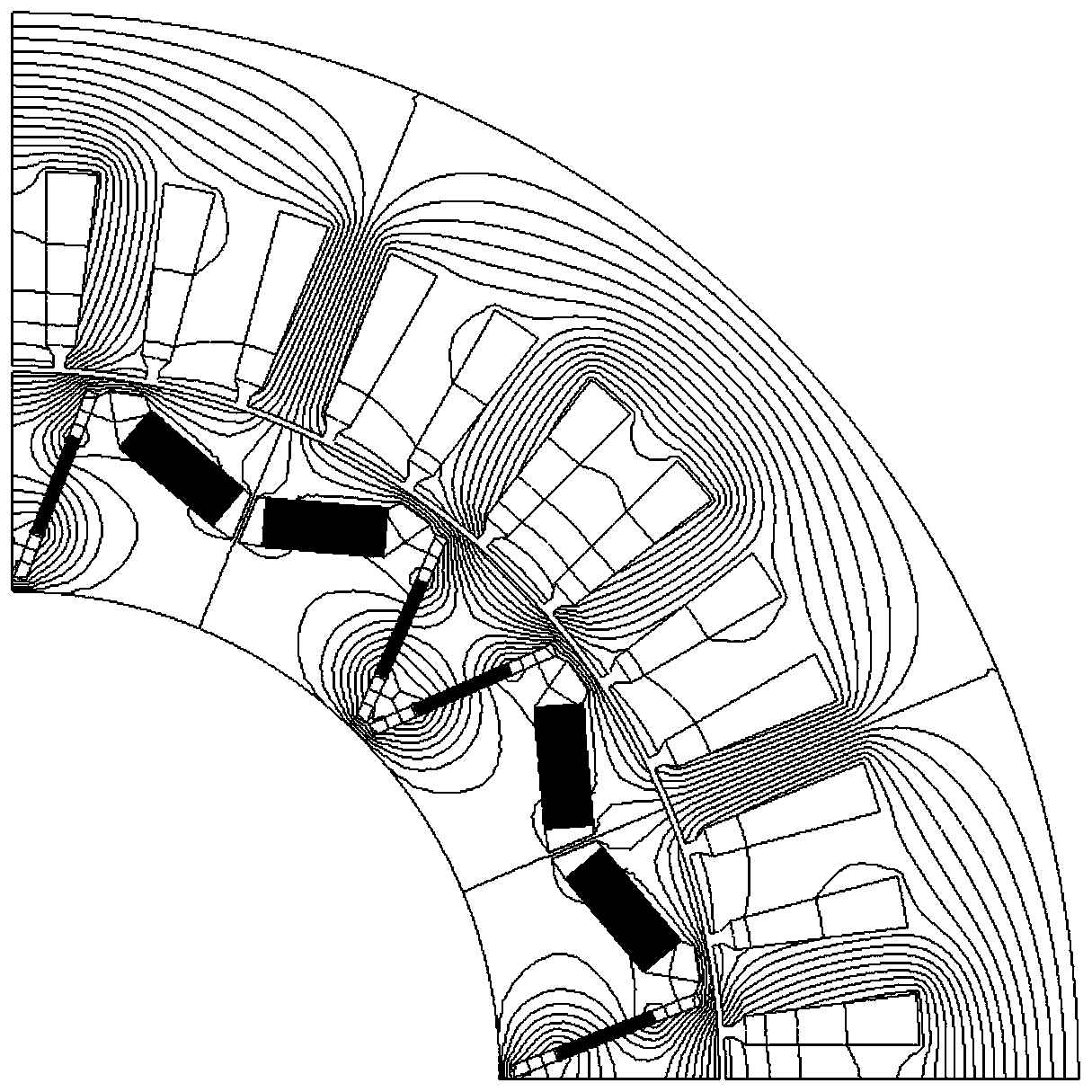
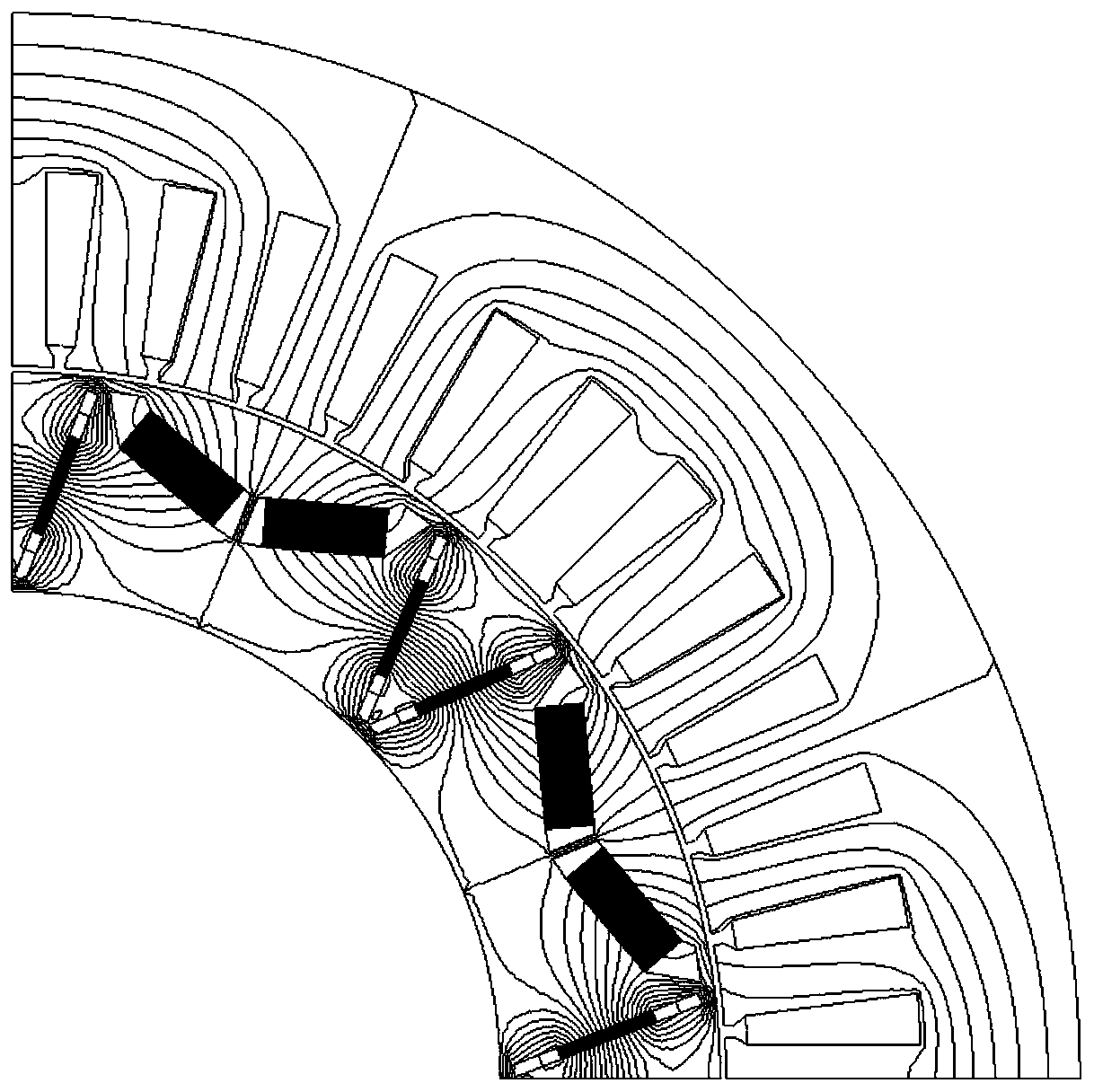
[0029] Specific implementation mode one: the following combination Figure 5 ~ Figure 8 To illustrate this embodiment, the double V-type hybrid permanent magnet adjustable flux memory motor of the present invention includes a stator core 1, an armature winding 2, a rotor core 3 and a rotating shaft 10; the rotor core 3 is fixed on the rotating shaft 10 and is located at Inside the stator core 1, the armature winding 2 is arranged on the stator core 1;
[0030] It is characterized in that it also includes a V-shaped low-coercivity permanent magnet slot 4, a low-coercivity permanent magnet 5, a V-shaped high-coercivity permanent magnet slot 6, a high-coercivity permanent magnet 7 and an additional magnetic flux path 8, 2P V-shaped low-coercive force permanent magnet slots 4 and 2P V-shaped high-coercive force permanent magnet slots 6 are alternately and uniformly arranged in the rotor core 3 along the circumferential direction, and P is the number of pole pairs of the stator arm...
specific Embodiment approach 2
[0035] Embodiment 2: The difference between this embodiment and Embodiment 1 is that the V-shaped included angle of the V-shaped low-coercive force permanent magnet slot 4 is 120 to 180 degrees; the V-shaped high-coercive force permanent magnet slot 6 The V-shaped included angle is 10-30 degrees.
[0036] When the V-shaped included angle of the V-shaped low-coercivity permanent magnet groove 4 is 180 degrees, a straight groove is formed, such as Figure 6As shown, a pair of low-coercivity permanent magnets 5 or a monolithic low-coercivity permanent magnet 5 can be installed side by side in the groove at this moment, when the V-shaped angle of the V-shaped low-coercivity permanent magnet groove 4 When being an angle other than 180 degrees, a low-coercivity permanent magnet 5 is respectively installed in two straight grooves, and there is an idle area at the bottom junction of the two low-coercivity permanent magnets 5, and the low-coercivity permanent magnet 5 A magnetic bridg...
specific Embodiment approach 3
[0037] Specific embodiment three: the difference between this embodiment and embodiment one or two is that the magnetization direction of the low-coercive force permanent magnet 5 is perpendicular to the long side of the radial section of the V-shaped low-coercive force permanent magnet groove 4, And the low-coercivity permanent magnets 5 in the same V-shaped groove are both N poles or S poles, and the magnetization directions of the low-coercivity permanent magnets 5 in two adjacent V-shaped grooves are opposite;
[0038] The magnetization direction of the high-coercivity permanent magnet 7 is perpendicular to the long side of the V-shaped high-coercivity permanent magnet groove 6 radial sections, and the magnetization direction of the high-coercivity permanent magnet 7 in the same V-shaped groove is opposite, the same The high-coercivity permanent magnet 7 in two straight slots of the V-shaped groove has the same magnetization direction as the respective adjacent low-coercivi...
PUM
 Abstract
Description
Claims
Application Information
 - R&D
- Intellectual Property
- Life Sciences
- Materials
- Tech Scout
- Unparalleled Data Quality
- Higher Quality Content
- 60% Fewer Hallucinations
Browse by: Latest US Patents, China's latest patents, Technical Efficacy Thesaurus, Application Domain, Technology Topic, Popular Technical Reports.
© 2025 PatSnap. All rights reserved.Legal|Privacy policy|Modern Slavery Act Transparency Statement|Sitemap|About US| Contact US: help@patsnap.com


