
Stress reducing thread form

A thread and thread surface technology, applied in threaded connections, threaded fasteners, bolts, etc., can solve problems such as loose connections, failures, and thread interface failures

Inactive Publication Date: 2019-05-24
FORUM US
View PDF9 Cites 2 Cited by
  • Summary
  • Abstract
  • Description
  • Claims
  • Application Information

AI Technical Summary

Problems solved by technology

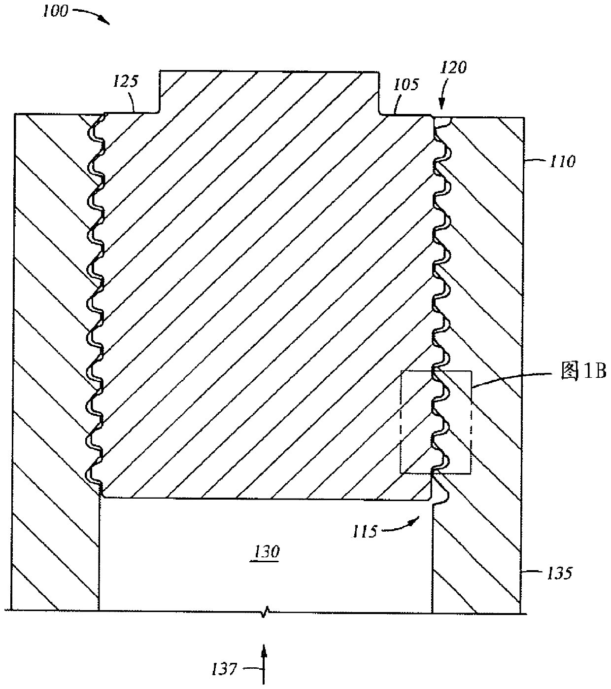
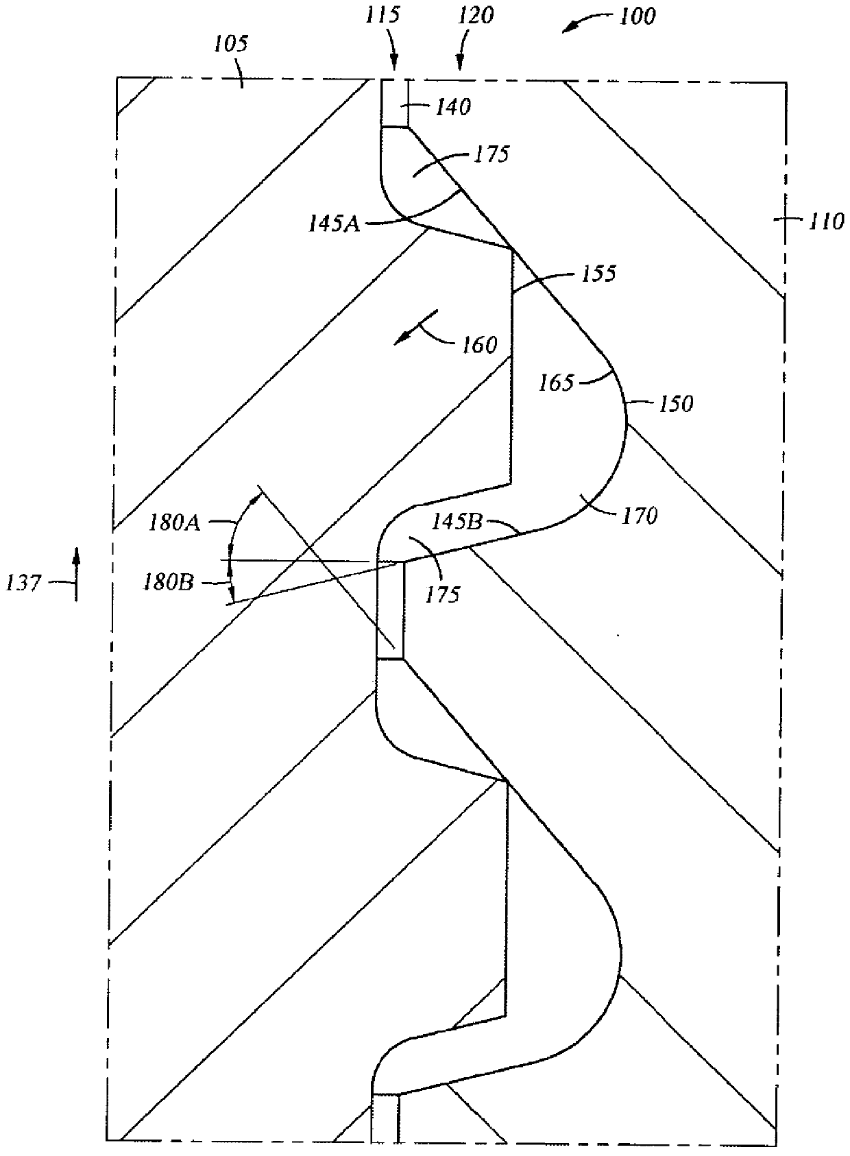
In particular, the threads are stressed along a shear plane that is substantially parallel to the longitudinal axis of the threads during operation of the fluid end, which leads to fatigue and ultimately failure of the thread interface
Additionally or alternatively, the threaded interface may experience vibrational forces which may lead to loosening and premature failure of the connection

Method used


Image

  • Stress reducing thread form
  • Stress reducing thread form
  • Stress reducing thread form

Examples


Embodiment Construction

[0013] Embodiments of the present disclosure overcome disadvantages of conventional threaded connections. In conventional threaded connections, the male and female threads are identical or similar in structure, which generates large shear stresses along the longitudinal axis of the threaded connection when subjected to cyclic tension. This high shear stress often causes the threaded connection to fail at the root of the thread upon fatigue. Additionally, the male and female thread structures of conventional threaded connections fit tightly together, which results in galling and / or hydrolocking.

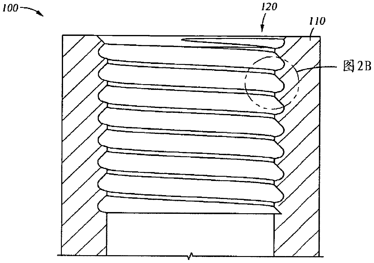
[0014] Embodiments of the present disclosure include stress relief threading. Embodiments of the present disclosure include threaded structures with improved fatigue life that can be used in cyclic loading situations, such as high pressure reciprocating pumps used in the oil and gas industry. Embodiments of the present disclosure include a threaded connection that includes a male th...


PUM


Abstract

A thread form for a threaded connection comprising a plurality of threads, wherein at least a portion of each of the threads comprise a root having a root radius that extends from a point central to the root and having planar flanks extending from both sides thereof.

Description

technical field [0001] Embodiments disclosed herein relate to threaded structures for coupling and decoupling threaded connections. More specifically, embodiments disclosed herein relate to a threaded configuration that reduces stress and improves fatigue life of threaded connections subjected to cyclic and / or vibration loading. Background technique [0002] Threaded connections are widely used in the oil and gas industry to connect one or more devices together. These types of threaded connections are often subjected to significant vibratory forces and / or significant cyclic loading. An example includes high pressure reciprocating pumps, such as multiplex piston pumps. These types of pumps have a fluid end, including valves, plungers, bushings, and other components, that is driven by a power end that converts rotation of a drive shaft into reciprocating motion of a plunger in the fluid end. These types of pumps pump fluid into the wellbore at rates of up to 10 barrels per ...

Claims


Application Information

Patent Timeline
Patent Type & Authority Applications(China)
IPC IPC(8): E21B17/042F16L15/06
CPCE21B17/0426F16L15/06E21B17/042E21B17/0423F16B33/00F16L15/006
Inventor W·弗雷德M·C·迪尔
Owner FORUM US
Learn More