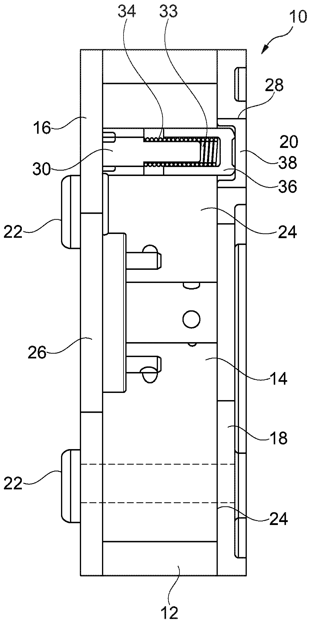
[0016] figure 1 An exemplary cam phaser 10 is shown. The cam phaser 10 is preferably used in combination with an engine (such as an internal combustion engine) to change the valve timing in a manner known in the art (for example, by hydraulic pressure). For example, the cam phaser 10 may be a vane unit type cam phaser. The cam phaser 10 preferably includes at least a stator 12, a rotor 14, a cover plate 16, a locking cover 18, a locking pin assembly 20 and a plurality of fasteners 22. Depending on the application, the cam phaser 10 may include additional components not described here. For example, some configurations may include components such as solenoids, torsion springs, housing members, cam members, shafts, and the like.
[0017] The rotor 14 is positioned in the stator 12 and rotates in the stator 12 (e.g., by hydraulic pressure) to change the valve timing in a manner known in the art. For example, a plurality of hydraulic chambers (not shown) may be formed between the rotor 14 and the blades of the stator 12, wherein the changing hydraulic pressure in the hydraulic chamber causes the rotor 14 to move within the stator 12. The cover plate 16 is positioned on one side of the stator 12 and the rotor 14, and the locking cover 18 is positioned on the opposite side of the stator 12 and the rotor 14. The stator 12, the cover plate 16 and the locking cover 18 preferably each include a plurality of first openings 24 for receiving fasteners 22 (e.g., bolts) when respectively aligned with each other. The rotor 14, the cover plate 16 and the locking cover 18 preferably each include a central opening 26. The locking cover 18 includes a second opening 28 for receiving a portion of the locking pin assembly 20, as will be described in further detail below.
[0018] The locking pin assembly 20 includes a pin 30, a spring 32, a movable locking member 36 and a bush 38. The pin 30 is preferably attached to the rotor 14 and can move together with the rotor 14. The movable lock 36 is positioned on the end of the pin 30 and can slide on the pin 30, and is biased to the extended position by the spring 32. Under certain conditions (for example, the hydraulic pressure is higher or lower than a threshold level), the movable lock 36 is biased into the cup-shaped bushing 38 by the spring 32. The reception of the movable lock 36 in the bushing 38 locks the rotor 14 into a specific position relative to the stator 12 until the lock pin assembly 20 is unlocked due to an increase in hydraulic pressure.
[0019] Figure 2A to Figure 2B The lock cover 18 is further shown. The locking cover 18 includes a body 40 formed of sheet metal, and the body 40 has a first axial side 42 and a second axial side 44. The first opening 24 is positioned to surround the body 40 and extends from the first axial side 42 to the second axial side 44. The central opening 26 of the locking cover 18 extends through the center of the body 40. The second opening 28 is formed at an appropriate position and extends from the first axial side 42 to the second axial side 44, and the second opening 28 receives the bushing 38 therein.
[0020] The lock cover 18 is formed of a metal sheet, and is more Figure 3A to Figure 3B The prior art locking plate of the locking cover 100 is thin, and the locking cover 18 includes a web portion 46. In order to provide additional strength and rigidity to the locking plate 100, some areas of the body 40 are thicker than most of the locking plate 100. These areas are referred to herein as reinforcements. For example, the locking cover 18 may include a rim 48 extending around the perimeter of the body 40. In addition, the locking cover 18 may also include bosses 50 and 52, which completely surround the first opening 24 and the second opening 28, respectively. These reinforcements provide increased rigidity to the areas (e.g. at the edges) that are likely to be most easily deformed or broken.
[0021] In the illustrated embodiment, the reinforcement is provided only on one side of the locking cover 18 (for example, the first axial side 42). In this way, the second axial side 44 is flat (ie, planar) on the entire side of the body 40, so that the locking cover 18 can be placed flat against the stator 12 and the rotor 14 (see figure 1 ). In other embodiments, the reinforcement portion may be formed on both the first axial side 42 and the second axial side 44 or only on the second axial side 44.
[0022] Such as figure 1 with Figure 2B As shown in the figure, the size of the locking cover 18 and the boss 52 can be set to match the size of the bushing 38. In other words, when the bush 38 is in the second opening 28, the open end of the bush is flush with the body 40 on the second axial side 44, and the closed end of the bush is flush with the body 40 on the first axial side 42 The body 40 (for example, the edge of the boss 52) is flush.
[0023] The exemplary disclosed locking cover 18 is preferably manufactured using a deep drawing and/or stamping process. In the exemplary disclosed process, a thin metal sheet blank is deep drawn to form reinforcements (e.g., rim 46 and bosses 50, 52). A stamping step is also performed to form the first opening 24, the central opening 26, and the second opening 28. This process produces a locking cover 18 that is significantly thinner than previous locking covers (eg, locking cover 100) while maintaining the strength and rigidity necessary to withstand the forces associated with the operation of the cam phaser 10.
[0024] In another process, the locking cover 18 and the cam phaser 10 are assembled together. The process may include: positioning the bushing 38 in the second opening 28; aligning the locking cover 18 with the rotor 14; and inserting the fastener 22 through the first opening 24. During operation, the bushing 38 is positioned such that the movable locking member 36 can be inserted into the bushing 38 to selectively lock the rotor 14 via the locking pin assembly 20.
[0025] Therefore, the disclosed locking cover 18 provides a thinner part that uses less raw materials (reduced costs), has a smaller mass, takes up less space, and can be passed through than previous locking covers More efficient process to manufacture.
[0026] Having described the currently preferred embodiments in detail in this way, it should be understood, and it will be obvious to those skilled in the art, that without changing the inventive concept and principle embodied in the present invention, it is possible to make Many physical changes, only some of these physical changes are exemplified in the detailed description of the present invention. It should also be understood that many embodiments combining only a part of the preferred embodiments are possible, and these embodiments do not change the inventive concept and principle embodied therein for those parts. Therefore, the embodiments and alternative configurations of the present invention are considered to be exemplary and/or illustrative, rather than restrictive in all aspects, and the scope of the present invention is determined by the appended claims rather than the foregoing description. It is specified, and therefore, all alternative embodiments and changes to the embodiments within the meaning and scope of equivalents of the claims will be included in the claims.
[0027] Parts list
[0028] 10. Cam phaser
[0029] 12. Stator
[0030] 14. Rotor
[0031] 16. Cover
[0032] 18.Lock the cover
[0033] 20. Locking pin assembly
[0034] 22. Fasteners
[0035] 24. The first opening
[0036] 26. Center opening
[0037] 28. Second opening
[0038] 30. Pin
[0039] 32. Spring
[0040] 34. Bearing
[0041] 36. Removable cover
[0042] 38. Bush
[0043] 40. Ontology
[0044] 42. The first axial side
[0045] 44. Second axial side
[0046] 46. Web
[0047] 48. Edge
[0048] 50. Boss
[0049] 52. Boss
[0050] 100. Lock the cover
[0051] 102. Ontology
[0052] 104. Through hole
[0053] 106. Through hole
[0054] 108. Second through hole
[0055] 110. Bush