Double-air-duct exhaust device and bowl washing machine

An exhaust device and double air duct technology, which is applied in the field of kitchen utensils, can solve the problems of high gas humidity, kitchen environment pollution, and large cabinet damage, and achieve the effects of reducing humidity, reducing pollution, and reducing damage.

Pending Publication Date: 2019-05-28
HANGZHOU ROBAM APPLIANCES CO LTD
0 Cites 0 Cited by

AI-Extracted Technical Summary

Problems solved by technology

[0005] The object of the present invention is to provide a double air duct exhaust device and a dishwasher to solve the problems in the prior art that the gas dis...

Method used

Concrete, as shown in Figure 3, housing 21 interior of driving mechanism 22 can be provided with accommodating groove 216, dividing plate 215 is two, accommodating groove 216 is positioned between two dividing plates 215, and driving mechanism 22 is embedded in Inside the receiving groove 216. The accommodating groove 216 acts as a limiter for the driving mechanism 22, which not only improves the installation accuracy of the driving mechanism 22, improves the matching accuracy between the driving mechanism 22 and the impeller 23, but also fixes the driving mechanism 22 to reduce the operating process. In the process, the driving mechanism 22 vibrates and the position shifts and the like occurs.
Concrete, the first air suction port 111 and the first air discharge port 112 are positioned at the two ends of the first air discharge channel 11 length direction respectively, to ensure the condensation stroke length of the first air discharge channel 11; The first air suction port 111 A head-end baffle may be provided at the place, and the head-end baffle faces the end where the first air suction port 111 is located, and the humid gas entering from the first air suction port 111 first flows to the corresponding end, and then turns to flow to the first air outlet 112, thereby further prolonging the condensation stroke length of the first air exhaust channel 11 and improving the condensation effect; The end baffle (the angle between the baffle 113 and the upstream side wall of the corresponding side wall is an obtuse angle), so as to ensure that the condensed water formed can flow down smoothly and flow into the return hole 114 at the end baffle when it flows through the middle baffle , to reduce the retention of condensed water caused by the intermediate baffle.
Concretely, all baffle plates 113 have overlapping parts in the cross-sectional projection of the width direction of the first air duct 11, thereby ensuring that the baffle plate 113 guides the condensed water, and ensures that the condensed water can flow to the end baffle. The backflow hole 114 can flow back to the interior of the inner tank through the backflow hole 114, thereby further reducing the damage caused by the outflow of condensed water to the curved components and the cabinet lamp.
In the present embodiment, as shown in Fig. 1 and Fig. 2, between the shell 21 of air duct part 1 and the wind-dispelling part 2, detachable affixation by buckle, specifically, can be on the air duct part 1 A clamp joint 13 is provided, and a clamp slot 218 is provided on the wind-dispelling component 2 , and the clamp slot 218 matches the clamp joint 13 . When installing, just press and snap the snap joint 13 of the air duct part 1 into the slot 218 of the wind driving part 2; when it needs to be disassembled, press the snap joint 13 inward and pull it out with force. In order to improve the communication and sealing performance between the air duct component 1 and the wind driving component 2, a third sealing ring 35 may also be provided at the connection.
In the present embodiment, as shown in Fig. 1 and Fig. 2, can be provided with the return hole 114 that can be communicated with the inside of liner on the first exhaust duct 11, the return hole 114 is positioned at the downstream of the first air suction port 111 . The droplets of humid gas condensing in the first row of air ducts 11 converge into water flow, and when they flow to the return hole 114, they can flow back from the return hole 114 to the interior of the liner, reducing condensed water on the basis of achieving the dehumidification effect The immersion caused by the outflow to the wind-dispelling component 2 and the cabinet can also reduce the trouble caused by the need to arrange a liquid contact container to receive the condensed water.
In the present embodiment, as shown in Figure 2 and Figure 3, can be provided with filter cover 217 at the second air inlet 213...

Abstract

The invention provides a double-air-duct exhaust device and a bowl washing machine, and relates to the technical field of kitchen appliances. The double-air-duct exhaust device comprises an air duct part and an air driving part which are connected with each other; a first exhaust channel and a second exhaust channel which are independent of each other are arranged in the air duct part; a first airsucking opening and a first exhaust opening are formed in the first exhaust channel; a second air sucking opening and a second exhaust opening are formed in the second exhaust channel; the bowl washing machine comprises a liner and the double-air-duct exhaust device; the double-air-duct exhaust device is arranged out of the liner and communicates with the interior of the liner through the first air sucking opening. According to the double-air-duct exhaust device, the moist gas exhausted from the liner is subjected to condensing treatment through cooling and colliding by the first exhaust channel; the moist gas in the first exhaust channel can be subjected to further cooling treatment through low-temperature air in the second exhaust channel, so that the condensing dehumidifying degree ofthe moist gas is further improved; therefore, the humidity of the gas exhausted from the liner is reduced, and the damage to a kitchen cabinet and the pollution of the environment caused by mildew ofthe kitchen cabinet are reduced.

Application Domain

Technology Topic

Image

  • Double-air-duct exhaust device and bowl washing machine
  • Double-air-duct exhaust device and bowl washing machine
  • Double-air-duct exhaust device and bowl washing machine

Examples

  • Experimental program(1)

Example Embodiment

[0026] The technical solutions of the present invention will be clearly and completely described below in conjunction with the accompanying drawings. Obviously, the described embodiments are part of the embodiments of the present invention, rather than all of them. Based on the embodiments of the present invention, all other embodiments obtained by those of ordinary skill in the art without creative work shall fall within the protection scope of the present invention.
[0027] In the description of the present invention, it should be noted that the terms "center", "upper", "lower", "left", "right", "vertical", "horizontal", "inner", "outer", etc. The indicated orientation or positional relationship is based on the orientation or positional relationship shown in the drawings, and is only for the convenience of describing the present invention and simplifying the description, rather than indicating or implying that the pointed device or element must have a specific orientation or a specific orientation. The structure and operation cannot therefore be understood as a limitation of the present invention. In addition, the terms "first" and "second" are only used for descriptive purposes, and cannot be understood as indicating or implying relative importance.
[0028] In the description of the present invention, it should be noted that the terms "installation", "connected" and "connected" should be understood in a broad sense, unless otherwise clearly specified and limited. For example, they can be fixed or detachable. Connected or integrally connected; it can be a mechanical connection or an electrical connection; it can be directly connected or indirectly connected through an intermediate medium, and it can be the internal communication between two components. For those of ordinary skill in the art, the specific meanings of the above-mentioned terms in the present invention can be understood in specific situations.
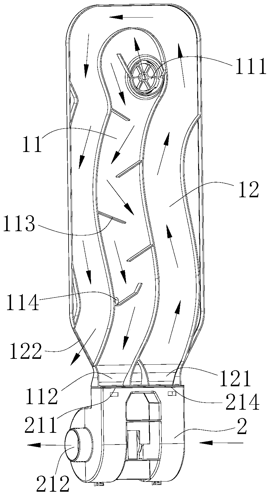
[0029] This embodiment provides a dual duct exhaust device, such as figure 1 with image 3 As shown, it includes an air duct component 1 and an air driving component 2 connected to each other. The air duct component 1 is provided with a first exhaust duct 11 and a second exhaust duct 12 that are independent of each other. The first exhaust duct 11 is provided with The first air suction port 111 communicating with the interior of the dishwasher and the first exhaust port 112 for communicating with the exterior of the dishwasher, the second exhaust duct 12 is provided with The second air inlet 121 connected to the outside and the second air outlet 122 used to communicate with the outside of the inner liner of the dishwasher; the blowing component 2 is used to drive the air inside the liner into the first air outlet through the first air inlet 111 11, and discharged through the first exhaust port 112; the air discharging component 2 is also used to drive the air outside the inner tank to flow into the second exhaust duct 12 through the second suction port 121, and be discharged through the second exhaust port 122 .
[0030] This embodiment also provides a dishwasher, which includes an inner tank and the above-mentioned dual-air duct exhaust device. The dual-air duct exhaust device is arranged outside the inner container, and the first suction port 111 communicates with the inside of the inner container.
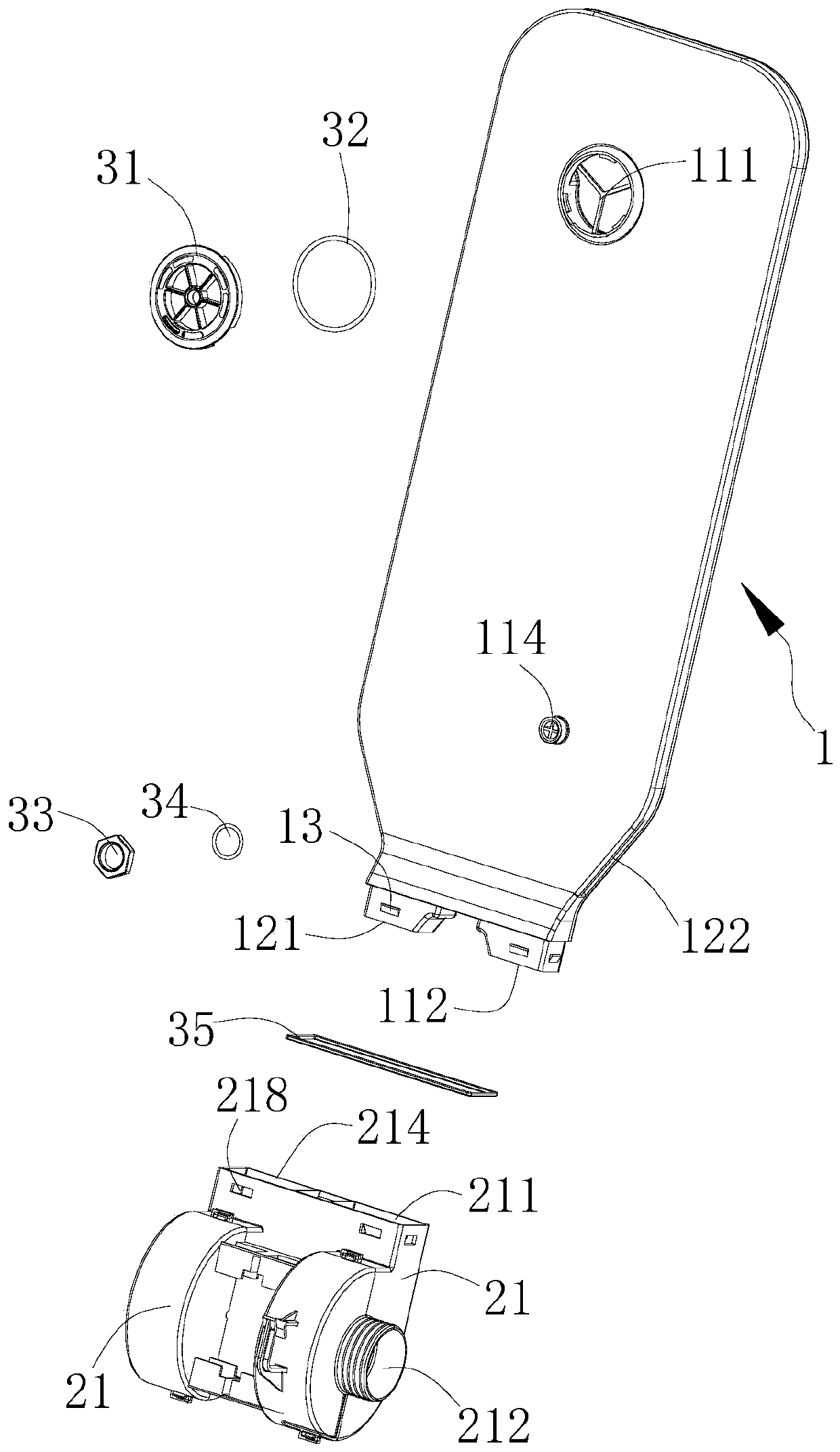
[0031] The dual-air duct exhaust device and dishwasher provided in this embodiment, wherein the dual-air duct exhaust device includes an air duct component 1 as a condensing channel for moist gas and a blower component 2 for driving the flow of gas. The air duct The component 1 includes a first exhaust duct 11 for the flow of humid gas in the inner container of the dishwasher to condense and dehumidify, and also includes a first exhaust duct 11 for the circulation of low-temperature air outside, so as to cool down the first exhaust duct 11 to promote moisture inside. The second exhaust duct 12 for gas condensation and dehumidification; wherein, the dishwasher includes an inner tank that provides washing space for tableware and the above-mentioned dual air duct exhaust device for discharging humid gas inside the inner tank and performing condensation and dehumidification treatment .
[0032] After the dishwasher is cleaned, the interior of the dishwasher is filled with high-temperature humid gas, and the blowing component 2 is turned on. On the one hand, the blowing component 2 drives the humid gas inside the dishwasher into the first row through the first suction port 111 Inside the air duct 11, and finally flow to the first exhaust port 112 to be discharged outside of the inner tank, the moist gas can exchange heat with its side wall during the process of flowing through the first exhaust duct 11, and the water vapor condenses into water droplets. Wall collision can also promote the condensation of water vapor into water droplets, thereby realizing the dehumidification of the humid gas, reducing the humidity of the exhaust gas, and correspondingly reducing the damage of the exhaust gas to the cabinet and the pollution of the environment caused by the mold of the cabinet. On the other hand, the blowing component 2 drives the low-temperature air outside the inner tank into the second exhaust duct 12 through the second suction port 121, and finally flows to the second exhaust port 122 for discharge; because the temperature of the low-temperature air is lower than that of the humid gas Therefore, the process of low-temperature air flowing through the second exhaust duct 12 exchanges heat with the moist gas in the first exhaust duct 11 through the side wall. The moist gas releases heat and cools to further promote the condensation and dehumidification, thereby further reducing the exhaust gas. High humidity, reduce the damage to the cabinets and the pollution of the environment caused by cabinet mildew.
[0033] In the dual air duct exhaust device, the first exhaust duct 11 of the air duct component 1 performs condensation treatment on the humid gas discharged from the inner bladder through cooling and collision, and the low-temperature air in the second exhaust duct 12 can affect the first exhaust The humid gas in the air duct 11 is further cooled to further increase the degree of condensation and dehumidification of the humid gas, thereby greatly reducing the humidity of the exhaust gas from the inner tank, and reducing the damage to the cabinet caused by the exhaust gas and the environmental pollution caused by the cabinet mold.
[0034] Specifically, the above-mentioned "low temperature air" refers to the ambient temperature outside the dishwasher, and it can be approximated that the ambient air temperature is about 25°C, and the temperature of the humid air inside the dishwasher is about 40°C ~ 50°C.
[0035] In this embodiment, such as figure 2 As shown, the first air suction port 111 of the air duct component 1 can protrude outward to form a first boss, which passes through the through hole on the liner and extends into the inside of the liner, and then passes through the first locking member 31 Lockingly fit with the first boss to fix the air duct component 1 on the inner liner; in addition, a first sealing ring 32 may be pressed between the first locking member 31 and the inner liner to increase the first air suction port 111 The tightness connected with the inner tank reduces the occurrence of moisture escape. Specifically, the first locking member 31 may be snap-fitted with the first boss, or may be screw-fitted.
[0036] In this embodiment, the first locking member 31 may include a locking ring and a filter rib provided in the locking ring, and the locking ring is connected to the first boss. When the moist gas inside the inner tank enters the first exhaust duct 11 through the first suction port 111, it needs to be filtered by the filter ribs, so as to block the impurities contained in the moist gas, so as to reduce the impact of the debris on the first suction port. 111 and the blockage caused in the first exhaust duct 11 to ensure the normal exhaust, condensation and dehumidification of the first exhaust duct 11.
[0037] In this embodiment, such as figure 1 As shown, the second air exhaust duct 12 may be arranged around the periphery of the first air exhaust duct 11. When the dual air duct exhaust device is in operation, the moist gas in the first exhaust duct 11 can exchange heat with the low-temperature air in the second exhaust duct 12 at its side walls. The heat exchange area is large and the condensation effect is good. Thereby, the dehumidification effect of the dual air duct exhaust device is further improved, the humidity of the exhaust gas is reduced, and the damage to the cabinet caused by the exhaust air is correspondingly reduced.
[0038] In this embodiment, such as figure 1 As shown, a baffle 113 may be provided on the inner wall of the first air exhaust duct 11, and the baffle 113 blocks the flow path of the first air exhaust duct 11 into a broken line shape. On the one hand, the setting of the baffle 113 can increase the actual flow length of the humid gas in the first exhaust duct 11, thereby prolonging the condensation time of the humid gas in the first exhaust duct 11, correspondingly improving its condensation effect, and reducing the exhaust air. On the other hand, when the humid gas flows through the first exhaust duct 11, it can collide with the baffle 113, and the small molecules of water vapor in the humid gas gather on the water droplets on the baffle 113, thereby further improving the dehumidification The effect is to reduce the humidity of the exhaust gas.
[0039] In this embodiment, such as figure 1 with figure 2 As shown, the first air exhaust duct 11 may be provided with a return hole 114 that can communicate with the inside of the inner liner, and the return hole 114 is located downstream of the first suction port 111. The droplets of the moist gas in the condensation stroke in the first exhaust duct 11 converge into a water stream, and when it flows to the return hole 114, it can return from the return hole 114 to the inside of the inner tank, reducing the condensation water on the basis of achieving the dehumidification effect The immersion caused by the external flow to the wind driving component 2 and the cabinet can also reduce the trouble caused by the need to set up a wetted container to receive the condensed water.
[0040] Specifically, in this embodiment, as figure 1 As shown, there may be multiple baffles 113. Along the flow direction of the first air exhaust duct 11, the multiple baffles 113 are staggered on the two opposite side walls of the first air exhaust duct 11, and are located at the end of the baffle. There is an acute angle between the plate 113 and the corresponding upstream side wall, and the return hole 114 is provided at the angle. Here is a specific form of setting the baffle 113 and the return hole 114. Specifically, along the flow direction of the first exhaust duct 11, the baffle 113 at the head end is the head end baffle, and the baffle 113 at the end is the end baffle. The baffle 113 between the plate, the head end baffle and the end baffle is an intermediate baffle, and the end baffle is set in the direction of the first suction port 111 (that is, there is an acute angle between the end baffle and the upstream side wall of the corresponding side wall Angle), the condensed water formed between the first suction port 111 and the end baffle flows to the angle between the end baffle and the corresponding side wall under the barrier of the end baffle, and then flows back to the inside through the return hole 114 The inside of the bladder, thereby further reducing the external flow of condensate water, and reducing the occurrence of immersion of the condensate water on the driving component 2 and the cabinet.
[0041] Specifically, the first air inlet 111 and the first air outlet 112 are respectively located at the two ends of the first air outlet 11 in the longitudinal direction to ensure the condensation stroke length of the first air outlet 11; the first air inlet 111 can be provided There is a head end baffle, the head end baffle faces the end where the first suction port 111 is located, and the moist gas entering from the first suction port 111 first flows to the corresponding end under the guiding action of the head end baffle. Then it turns and flows to the first exhaust port 112, thereby further extending the condensation stroke length of the first exhaust duct 11 and improving the condensation effect; the middle baffle between the first end baffle and the end baffle is arranged in the direction of the end baffle (The angle between the baffle 113 and the upstream side wall of the corresponding side wall is an obtuse angle) to ensure that when the formed condensate flows through the middle baffle, it can flow down smoothly and flow into the return hole 114 at the end baffle to reduce The condensate caused by the intermediate baffle remains.
[0042] Specifically, the cross-sectional projections of all baffles 113 in the width direction of the first exhaust duct 11 overlap, so as to ensure that the baffles 113 guide the condensed water and ensure that the condensed water can flow to the return holes 114 on the end baffles. It can flow back to the inside of the liner through the return hole 114, thereby further reducing the damage to the wind part and the cabinet light caused by the outflow of condensed water.
[0043] Specific, such as figure 2 As shown, the return hole 114 can protrude outward to form a second boss, the second boss passes through the corresponding through hole on the inner liner and extends into the inner liner, and then engages with the second boss through the second locking member 33 In cooperation, on the basis of realizing the communication between the return hole 114 and the inner liner, the air duct member 1 is further fixed to improve the firmness of the air duct member 1 fixed on the inner liner. Specifically, an external thread may be provided on the outer wall of the second boss, the second locking member 33 is a nut, and the nut is threaded with the second boss to achieve a locking connection.
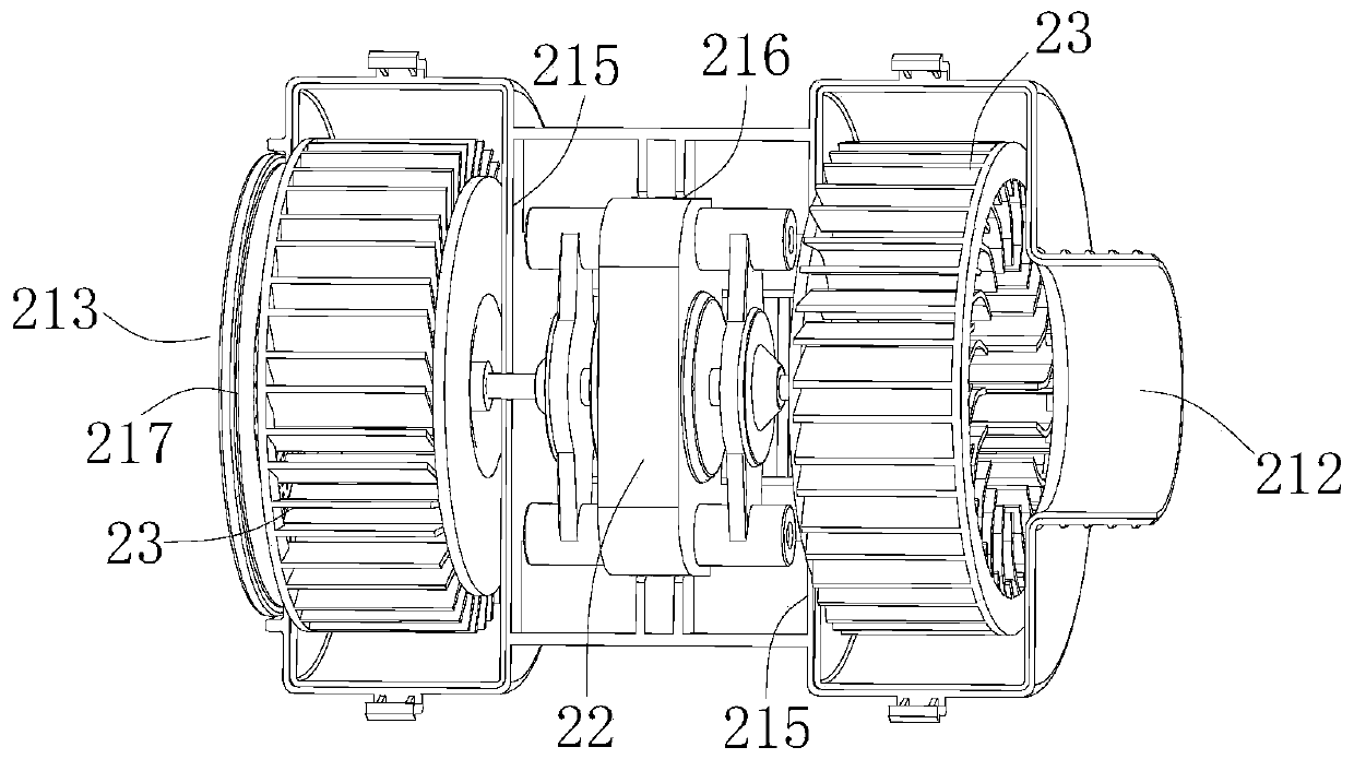
[0044] In this embodiment, such as figure 2 with image 3 As shown, the wind driving component 2 may include a housing 21, a driving mechanism 22, and two impellers 23. The two impellers 23 are installed inside the housing 21. The driving mechanism 22 is connected to the impeller 23 for driving the impeller 23 to rotate; the housing 21 is provided with There are a first air inlet 211 and a first air outlet 212 corresponding to one of the impellers 23, a second air inlet 213 and a second air outlet 214 corresponding to the other impeller 23, and a first air outlet 112 It communicates with the first air inlet 211; the second air inlet 121 communicates with the second air outlet 214, or the second air outlet 122 communicates with the second air inlet 213. Here is a specific form of the blowing component 2. When a dual-air duct exhaust device is required, the driving mechanism 22 is controlled to drive the impeller 23 to rotate. The flow direction of the humid gas in the first exhaust duct 11 is fixed, and the impeller 23 drives the inner The humid gas inside the bladder flows through the first air inlet 111, the first air exhaust duct 11, the first air outlet 112 and the first air inlet 211 in sequence, then flows into the housing 21, and is discharged through the first air outlet 212; , The flow of low-temperature air in the second exhaust duct 12 includes two situations: figure 1 As shown, the second air inlet 121 of the second air exhaust duct 12 is in communication with the second air outlet 214 of the driving component 2, and the impeller 23 drives the external air into the housing 21 through the second air inlet 213 and passes through the second air outlet 214 and the second suction port 121 enter the second exhaust duct 12, and then are discharged through the second exhaust port 122; or, the second exhaust port 122 of the second exhaust duct 12 and the second intake of the air driving component 2 The air port 213 is connected, and the impeller 23 drives the low-temperature air to flow through the second air inlet 213, the second air outlet 12, the second air outlet 122 and the second air inlet 213 in sequence, and then flow into the housing 21 and pass through the second air inlet 213. The air outlet 214 is discharged, so as to realize the driving of the air flow in the two air exhaust ducts by the driving component 2 at the same time.
[0045] Specifically, for the first air outlet 112 to communicate with the first air inlet 211, and the second air inlet 121 to communicate with the second air outlet 214, the two impellers 23 drive the airflow in opposite directions, and two driving mechanisms 22 may be provided separately. To drive one of the impellers 23, a driving mechanism 22 can also be provided to synchronously drive the two impellers 23 to rotate synchronously. By adjusting the setting direction and position of the blades on the impeller 23, the air flow direction is reversed; for the first air outlet 112 and the first inlet The air port 211 is connected, and the second air outlet 122 is connected to the second air inlet 213. The two impellers 23 drive the air flow in the same direction. Two driving mechanisms 22 can be provided to drive one of the impellers 23 separately, or a driving mechanism can be provided. 22 synchronously drives the two impellers 23 to rotate synchronously.
[0046] In this embodiment, such as figure 1 with figure 2 As shown, the air duct component 1 and the housing 21 of the air displacing part 2 are detachably fastened by a buckle. Specifically, the air duct part 1 may be provided with a clamping joint 13 and the air displacing part 2 is provided The card slot 218 is matched with the card connector 13. When installing, press the card connector 13 of the air duct component 1 into the card slot 218 of the air discharging component 2; when it needs to be disassembled, press the card connector 13 inward and pull it out forcefully. In order to improve the communication and sealing performance between the air duct component 1 and the air displacing component 2, a third sealing ring 35 may also be provided at the connection.
[0047] In this embodiment, such as image 3 As shown, a partition 215 may be provided in the housing 21, and the partition 215 blocks the two impellers 23 in two relatively independent chambers. When the driving part 2 is running, the two impellers 23 are respectively located in relatively independent chambers to rotate, so as to ensure the independence of the two airflows in the driving part 2 and reduce the mutual turbulence of the two airflows in the housing 21 and affect the driving of the wind The blowing effect of the component 2 and the mixed flow of the discharged moist gas with the external low temperature air affects the cooling and condensation effect of the low temperature air on the moist gas.
[0048] In this embodiment, such as image 3 As shown, the driving mechanism 22 is installed inside the housing 21 and located between the two impellers 23. The driving mechanism 22 includes two driving ends, and the two driving ends are connected to the two impellers 23 in a one-to-one correspondence. Here is the specific arrangement form when a driving mechanism 22 is installed. The driving mechanism 22 is installed inside the casing 21 between the two impellers 23. On the basis of realizing the synchronous driving of the two impellers 23, on the one hand, compared with the driving mechanism 22 Externally, it can reduce the space occupation; on the other hand, compared with the drive mechanism 22 arranged on one side of the two impellers 23, the transmission distance of the drive mechanism 22 to the outer impeller 23 is larger, and the corresponding torque is larger. It is easy to be damaged. The driving mechanism 22 is located between the two impellers 23, and the distance between the two driving ends on both sides of the impeller 23 corresponds to the smaller transmission distance between the impellers. The driving mechanism 22 has higher driving efficiency and longer service life; On the one hand, the housing 21 can protect the driving mechanism 22 to reduce damage to the driving mechanism 22 caused by external factors.
[0049] Specific, such as image 3 As shown, the housing 21 of the driving mechanism 22 may be provided with a receiving groove 216 in which there are two partitions 215, the receiving groove 216 is located between the two partitions 215, and the driving mechanism 22 is embedded in the receiving groove 216. The accommodating groove 216 plays a role in limiting the driving mechanism 22, which can not only improve the installation accuracy of the driving mechanism 22 and the matching accuracy between the driving mechanism 22 and the impeller 23, but also fix the driving mechanism 22 to reduce the operation process. In this case, the driving mechanism 22 vibrates and causes positional deviation.
[0050] In this embodiment, as figure 2 with image 3 As shown, a filter cover 217 may be provided at the second air inlet 213 of the housing 21, and the filter cover 217 filters the external air entering the second air inlet 213, so as to reduce the impact of impurities in the external air on the housing. The blockage caused by the impeller 23 inside 21, etc., ensures the normal use of the driving component 2 and the air duct component 1.
[0051] Finally, it should be noted that the above embodiments are only used to illustrate the technical solutions of the present invention, not to limit them; although the present invention has been described in detail with reference to the foregoing embodiments, those of ordinary skill in the art should understand that: The technical solutions described in the foregoing embodiments are modified, or some or all of the technical features are equivalently replaced; these modifications or replacements do not cause the essence of the corresponding technical solutions to deviate from the scope of the technical solutions of the embodiments of the present invention.

PUM

no PUM

Description & Claims & Application Information

We can also present the details of the Description, Claims and Application information to help users get a comprehensive understanding of the technical details of the patent, such as background art, summary of invention, brief description of drawings, description of embodiments, and other original content. On the other hand, users can also determine the specific scope of protection of the technology through the list of claims; as well as understand the changes in the life cycle of the technology with the presentation of the patent timeline. Login to view more.

Similar technology patents

Swimming goggle

ActiveUS20190381361A1Optimal level of comfort and efficacyReduce humidityDetails involving processing stepsImage analysisEngineering
Owner:ADIDAS

Classification and recommendation of technical efficacy words

  • Reduce pollution
  • Reduce humidity

Pollution credit method using electronic networks

InactiveUS6601033B1Reduce pollutionSustainable waste treatmentFinanceThird partyEngineering
Owner:SOWINSKI RICHARD F
Why Eureka
Try Eureka